
Novel dual-voltage quick response brake rectifier

A fast-response, rectifier technology, applied in the direction of converting AC power input to DC power output, emergency protection circuit devices for limiting overcurrent/overvoltage, and output power conversion devices, which can solve the output response speed of brake rectifiers. Slow, rotating shaft lock and other problems, to achieve the effect of shortening the lock-up time, increasing the service life, and fast response

Pending Publication Date: 2018-08-17
苏州采奕动力科技有限公司
View PDF0 Cites 0 Cited by
  • Summary
  • Abstract
  • Description
  • Claims
  • Application Information

AI Technical Summary

Problems solved by technology

[0006] The technical problem to be solved by the present invention is to provide a new dual-voltage fast-response brake rectifier, which solves the problems of the slow output response speed of the brake rectifier in the prior art and the problem that the rotating shaft is easily blocked and locked instantly.

Method used


Image

  • Novel dual-voltage quick response brake rectifier

Examples


specific Embodiment

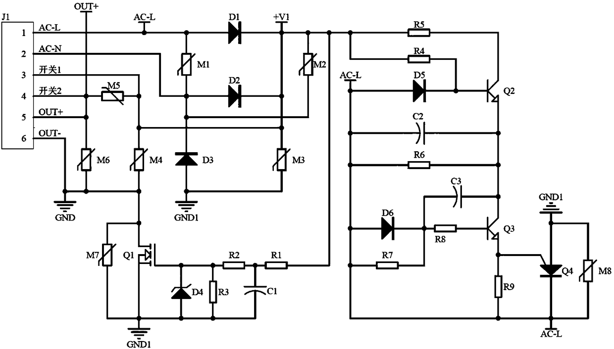
[0037] Such as figure 1 as shown,

[0038] The half-wave rectifier circuit is mainly composed of diode D1, diode D2 and diode D3. The cathode of diode D1 and the cathode of diode D2 are electrically connected with switch 1. The anode of diode D1 is connected with an input terminal AC-L of the AC power supply. The diode The anode of D2 and the cathode of diode D3 are electrically connected to the other input terminal AC-N of the AC power supply.

[0039] The MOS tube trigger circuit is mainly composed of resistor R1, resistor R2, resistor R3, capacitor C1, Zener diode D4 and MOS tube Q1, one end of resistor R1 is electrically connected to the cathode of diode D1, the other end of resistor R1, one end of resistor R2 It is electrically connected with the anode of capacitor C1, the other end of resistor R2, one end of resistor R3, the cathode of Zener diode D4, and the gate G of MOS transistor Q1 are electrically connected with each other, and the drain D of MOS transistor Q1 is ...


PUM


Abstract

The invention discloses a novel dual-voltage quick response brake rectifier. The brake rectifier includes a half-wave rectifier circuit, an MOS pipe trigger circuit, a silicon controlled rectifier trigger circuit, a switch contact circuit, an output contact circuit, and a protection circuit. The half-wave rectifier circuit is used for carrying out half-wave rectification on the input of an alternating current power supply. The MOS pipe trigger circuit is used for controlling switching on and switching off of circuit output of the rectifier so as to achieve an effect of quick braking or releasing of the rectifier. The silicon controlled rectifier trigger circuit urges the rectifier to form dual voltage output when the rectifier is just energized, and so a response action is made to accelerate the braking or releasing and blocking and holding time of a rotating shaft is shortened, therefore, service lives of a magnetic brake and the rotating shaft are increased. The switch contact circuit is connected to an external control circuit and controls the output of the rectifier through the external control circuit. All key electric signal contacts, MOS pipes and silicon controlled rectifiers are provided with voltage-sensitive resistors in order to eliminate external interference factors as much as possible.

Description

technical field [0001] The invention belongs to the field of electromagnetic braking rectifiers, and in particular relates to a novel double-voltage fast-response braking rectifier. Background technique [0002] Electromagnetic brakes need to operate quickly when the rectifier is powered on and off when the use requirements are very strict, so as to prevent the locking of the rotating shaft from occurring, and at the same time need to achieve the effect of fast braking or release. [0003] When the initial power-on voltage of the electromagnetic brake is within its rated voltage range, the higher the voltage at this time, the faster the response speed of its braking or releasing action. At present, there are two types of rectifiers commonly used in electromagnetic brakes. The first is the rectifier There are only four terminals, single voltage output, and can only realize the function of slow braking or release at the same time; These two terminals of the external contactor...

Claims


Application Information

Patent Timeline
Patent Type & Authority Applications(China)
IPC IPC(8): H02M7/217H02H9/04
CPCH02H9/04H02M7/217
Inventor 唐书峰艾志勇
Owner 苏州采奕动力科技有限公司
Learn More