
One-way heat transfer structure based on material thermal expansion difference and application method

A technology of thermal expansion and thermal expansion rate, which is applied in the field of one-way heat transfer devices, can solve the problems of thickened permafrost layers, inappropriateness, and high cost of thermal diodes, and achieve the effects of cost reduction, simple structure, and increased application range

Active Publication Date: 2018-08-17
NANJING UNIV OF AERONAUTICS & ASTRONAUTICS
View PDF7 Cites 0 Cited by
  • Summary
  • Abstract
  • Description
  • Claims
  • Application Information

AI Technical Summary

Problems solved by technology

The traditional one-way heat transfer device is a thermal diode. Zhu Jinqiu and others reported in "Logic Research", 1992(2):94-99 that this thermal diode is tubular in shape, and in some specific occasions, such as realizing two cavity The shape of the one-way heat transfer between bodies is not suitable; due to the use of gravity, there is a requirement for the placement method. Patent CN200410036758.7 discloses a one-way heat conduction device, which vertically Inserted in the permafrost zone of the Qinghai-Tibet Highway, when the temperature of the underground soil layer is high and the temperature above the ground is low, the gas in the heat pipe has a high density on the top and a low density on the bottom, and the gas in the heat pipe generates convection to release high heat from the underground soil layer; When the temperature is low and the temperature on the ground is high, the density of the gas in the heat pipe is small on the top and high on the bottom. The gas in the heat pipe does not produce convection, which plays a role in thickening the permafrost layer. However, if the heat pipe is placed horizontally, there is no one-way heat conduction nature; and the cost of traditional thermal diodes is high, which is not conducive to large-scale use

Method used


Image

  • One-way heat transfer structure based on material thermal expansion difference and application method
  • One-way heat transfer structure based on material thermal expansion difference and application method
  • One-way heat transfer structure based on material thermal expansion difference and application method

Examples


Embodiment 1

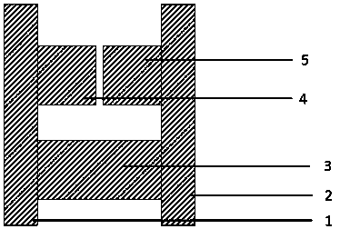
[0028] The structure includes a partition 1, a partition 2, a support column 3 and a heat transfer column. The heat transfer column is composed of a heat transfer half column 4, a heat transfer half column 5 and the gap between the two half columns; the heat transfer half column 4, 5 and the support column 3 are placed between the two partitions, and the support column 3 mechanically connects and fixes the partitions 1 and 2.

[0029] The theoretical model of the ideal one-way heat transfer structure is given below. Assuming that the length of the heat transfer half column is L, the thermal expansion coefficients of the left and right heat transfer half columns are respectively C L and C R , the length of the support column is 2L, and the thermal expansion rate is C, where C L >C>C R , the reference temperature is T 0 , the gap between the left and right heat transfer semi-columns is S at the reference temperature. Assuming that the thermal expansion rate of the support c...

Embodiment 2

[0041] The structure includes a partition 1, a partition 2, a support column 3 and a heat transfer column. The heat transfer column is composed of a heat transfer half column 4, a heat transfer half column 5 and the gap between the two half columns; the heat transfer half column 4, 5 and the support column 3 are placed between the two partitions, and the support column 3 mechanically connects and fixes the partitions 1 and 2.

[0042] The theoretical model of the ideal one-way heat transfer structure is given below. Assuming that the length of the heat transfer half column is L, the thermal expansion coefficients of the left and right heat transfer half columns are respectively C L and C R , the length of the support column is 2L, and the thermal expansion rate is C, where C L >C>C R , the reference temperature is T 0 , the gap between the left and right heat transfer semi-columns is S at the reference temperature. Assuming that the thermal expansion rate of the support c...

Embodiment 3

[0054] The structure includes a partition 1, a partition 2, a support column 3 and a heat transfer column. The heat transfer column is composed of a heat transfer half column 4, a heat transfer half column 5 and the gap between the two half columns; the heat transfer half column 4, 5 and the support column 3 are placed between the two partitions, and the support column 3 mechanically connects and fixes the partitions 1 and 2.

[0055] The theoretical model of the ideal one-way heat transfer structure is given below. Assuming that the length of the heat transfer half column is L, the thermal expansion coefficients of the left and right heat transfer half columns are respectively C L and C R , the length of the support column is 2L, and the thermal expansion rate is C, where C L >C>C R , the reference temperature is T 0 , the gap between the left and right heat transfer semi-columns is S at the reference temperature. Assuming that the thermal expansion rate of the support c...


PUM


Abstract

The invention discloses a one-way heat transfer structure and an application method, and belongs to the field of one-way heat transfer devices. The one-way heat transfer structure can be randomly placed without affecting the effect. The structure comprises partition plates, a support column and heat transfer half columns, wherein the heat transfer half columns and the support column are placed between the partition plates; the support column is mechanically and fixedly connected with the partition plates, the partition plated are made of a high-thermal-conductivity material, and the supportingcolumn is made of a material with a low heat conductivity and a certain mechanical strength; two materials with high heat conductivity but different thermal expansion rates are selected by the partition plates on the two sides, the thermal expansion rate of the left heat transfer half column is higher than the thermal expansion rate of the right heat transfer half column, and the thermal expansion rate of the support column is between the thermal expansion rates of the heat transfer half columns on the two sides; a small gap is reserved between the heat transfer half columns, when the left side partition plate is a hot end, the right side partition plate is a cold end, when the temperature difference exceeds a critical value, tiny gaps between the heat transfer half columns will disappear, and the whole structure can conduct heat conduction well; and the left side partition plate is a cold end, the right side partition plate is a hot end, a gap is reserved between the heat transfer half columns, and the partition plates are low in heat conduction.

Description

technical field [0001] The invention belongs to the field of one-way heat transfer devices, and in particular relates to a one-way heat transfer structure based on differences in thermal expansion of materials and a use method. Background technique [0002] A unidirectional heat transfer device is a device capable of unidirectional heat conduction, that is, the device has high thermal conductivity under a forward temperature difference and is almost an adiabatic material under a reverse temperature difference. The one-way heat transfer device has important application value in space technology, low-temperature refrigeration and solar energy, and has played an important role in modern industry and life. Recently, as the requirements for environmental protection, energy saving and new energy are getting higher and higher, unidirectional heat transfer devices will be more valuable. The traditional one-way heat transfer device is a thermal diode. Zhu Jinqiu and others reported ...

Claims


Application Information

Patent Timeline
Patent Type & Authority Applications(China)
IPC IPC(8): F28D21/00F28F21/00
CPCF28D21/00F28F21/00
Inventor 胡知力菅磊张助华轩啸宇
Owner NANJING UNIV OF AERONAUTICS & ASTRONAUTICS
Learn More