Projection equipment for aided teaching

A technology of projection equipment and auxiliary teaching, applied in mechanical equipment, educational appliances, optics, etc., can solve the problems of performance degradation, affecting the brightness performance of LCD projectors, light loss, etc., and achieve the effect of overcoming a single function.

Pending Publication Date: 2018-08-10
ZHAOQING UNIV
View PDF1 Cites 2 Cited by
  • Summary
  • Abstract
  • Description
  • Claims
  • Application Information

AI Technical Summary

Problems solved by technology

The optical signal output by the CRT is irradiated on the photoelectric converter, and the optical signal is converted into a continuously changing electrical signal: an external light source generates a beam of strong light, which is projected on the liquid crystal light valve, reflected by the internal mirror, and passed through the optical modulator. Changing its optical characteristics, the polarizing filter following the light valve will filter out the light in other directions, and only allow the light in the same direction as its optical slit to pass through. This light is recombined with the CRT signal and projected onto the large screen. It is the projector with the highest brightness and resolution so far, with a brightness of up to 6000 lumens and a resolution of 2500×2000. It is suitable for occasions with strong ambient light and many audiences, such as super-large-scale command centers, conference centers and large-scale entertainment The location, but its price is high, the volume is large, and the light valve is not easy to maintain. The main brands are: Hughes-JVC, Ampro, etc. The imaging device of the liquid crystal panel projector is a liquid crystal panel, which is also a passive projection method, using an external light source Metal halide lamp or UHP (cold light source), if it is designed with three LCD panels, the strong light will

Method used


Image

  • Projection equipment for aided teaching
  • Projection equipment for aided teaching
  • Projection equipment for aided teaching

Examples


Embodiment Construction

[0020] The following will clearly and completely describe the technical solutions in the embodiments of the present invention with reference to the accompanying drawings in the embodiments of the present invention. Obviously, the described embodiments are only some, not all, embodiments of the present invention. Based on the embodiments of the present invention, all other embodiments obtained by persons of ordinary skill in the art without making creative efforts belong to the protection scope of the present invention.

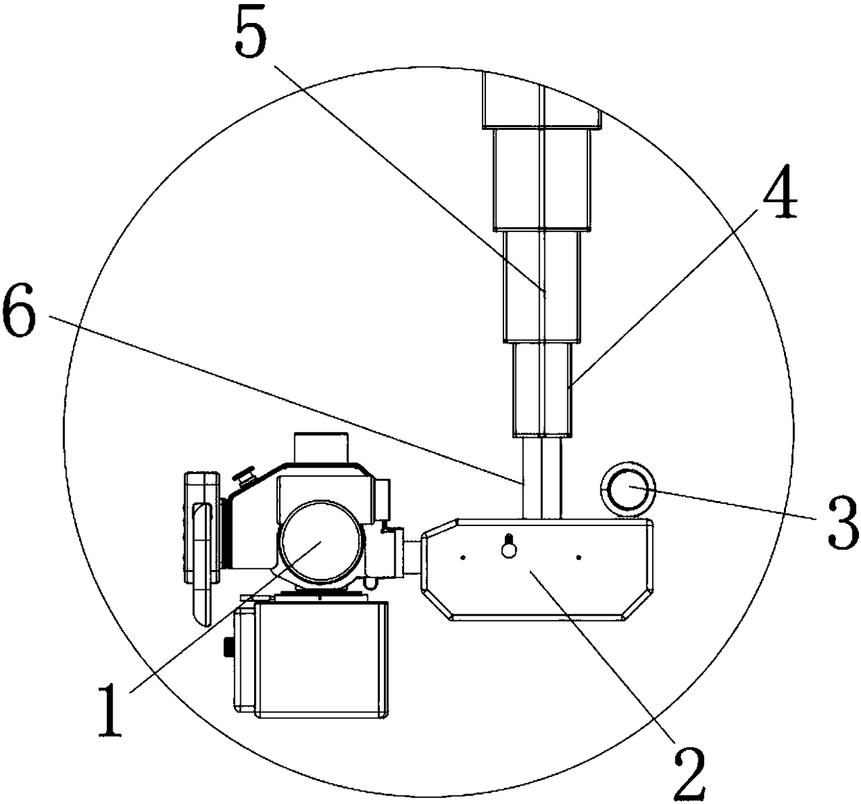
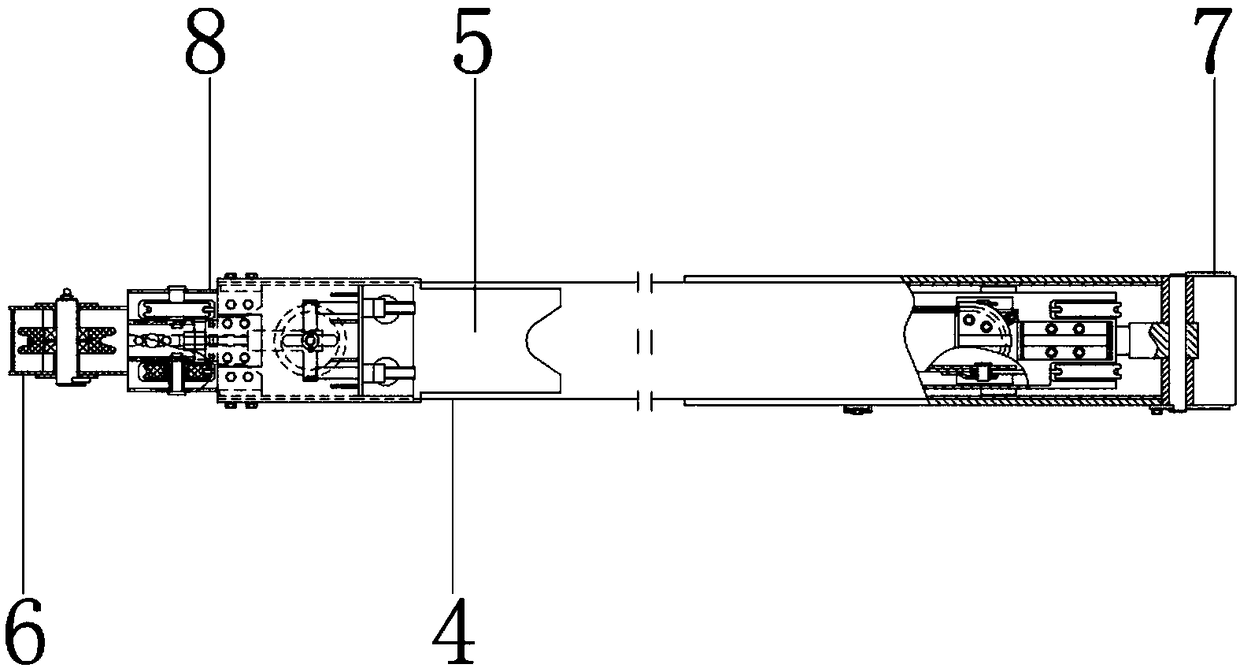
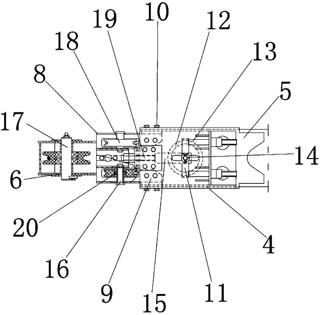
[0021] see Figure 1-4 , the present invention provides a technical solution: a projection device for auxiliary teaching, including a projector 1, the projector 1 is used for auxiliary teaching projection demonstration, the right side of the projector 1 is provided with a fixing seat 2, and the fixing seat 2 is used for adjusting The vertical rotation angle of the projector 1, the upper surface of the fixed seat 2 is equipped with a fixed ring 3, which is used...


PUM


Abstract

The invention discloses projection equipment for aided teaching. The projection equipment comprises a projector, a fixing base is arranged on the right side of the projector, the inner wall of the fixing base and the outer wall of the projector are in overlapping connection, an inner rod is installed on the inner wall of the fixing base, the outer wall of the inner rod and the outer wall of the fixing base are in overlapping connection, an outer rod is arranged on the outer wall of the inner rod, a sliding plate is installed on the inner wall of the outer rod, and the outer wall of the slidingplate and the inner wall of the outer rod are in overlapping connection. According to the projection equipment, through cooperation of a fixing ring, the inner rod and the outer rod under the actionof the fixing base, the problems that the cost of purchasing teaching aids of a school is increased and projection equipment easily causes the work fatigue of instructors and maintenance workers in the use are avoided, the efficiency of learning and use of teachers and students is improved, the work fatigue of the teachers during the lectures is avoided, the use expenses of purchasing teaching aids are saved, the waste of the teaching aids is avoided, and the projection equipment is suitable for popularization and use.

Description

technical field [0001] The invention relates to the technical field of teaching aids, in particular to a projection device for auxiliary teaching. Background technique [0002] So far, relatively advanced projectors that are widely used in teaching, conferences, and demonstrations are mainly realized through three display technologies, namely, CRT (cathode ray tube) projection technology, LCD (liquid crystal display) projection technology, and recently developed projectors. CRT is the abbreviation of English Cathode Ray Tube, translated as cathode ray tube. As an imaging device, it is the earliest and most widely used display technology. This kind of projector can decompose the input signal source into three colors of R (red), G (green) and B (blue) and project them to the CRT tube. On the fluorescent screen, the fluorescent powder is enlarged and converged by the light-emitting system under high pressure, and a color image is displayed on the screen. This kind of projector...

Claims


Application Information

Patent Timeline
IPC IPC(8): G09B5/02G03B21/54F16M13/02F16M11/12F16M11/28
CPCG09B5/02F16M11/12F16M11/28F16M13/02G03B21/54
Inventor 王一李云鹤曾舒莹
Owner ZHAOQING UNIV
Why Eureka
Try Eureka