Reciprocating pneumatic valve, air cylinder with same and grease pump
A technology of reciprocating cylinders and pneumatic valves, applied in the direction of engine lubrication, valve devices, lubrication pumps, etc., can solve problems such as inconvenient installation, easy wear, and failure of butter pumps
- Summary
- Abstract
- Description
- Claims
- Application Information
AI Technical Summary
Problems solved by technology
Method used
Image
Examples
Embodiment 1
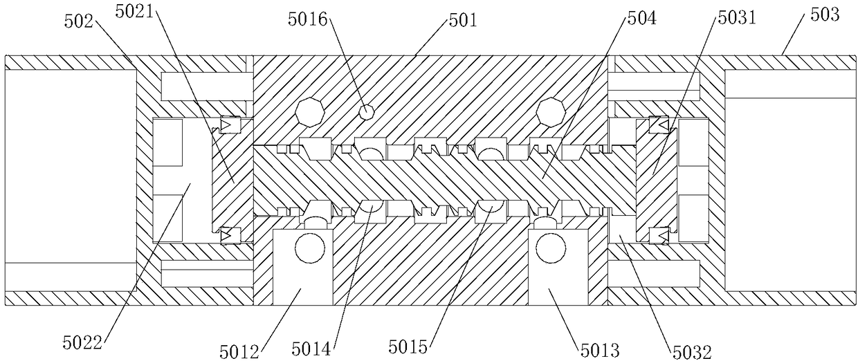
[0066] Such as Figure 1 to Figure 6 As shown, the reciprocating pneumatic valve includes a main valve body 501, a reversing mandrel 504, a left valve body 502 and a right valve body 503, and the left valve body 502 and the right valve body 503 are respectively fixed on both sides of the main valve body 501. The reversing core rod 504 is movably installed in the reversing core hole 505 of the main valve body 501;
[0067] Such as figure 1 As shown, the top of the main valve body 501 is provided with an air inlet 5011, and the bottom is provided with a left air outlet 5014, a left reversing hole 5016, a right air outlet 5015 and a right reversing hole 5017, and the side of the main valve body 501 is left to exhaust hole 5012 and right exhaust hole 5013;
[0068] When the reversing mandrel 504 is on the left valve body 502 side, it communicates with the air inlet 5011 and the right air outlet 5015 and the left air outlet 5014 and the left air outlet 5012. The air hole 5011 an...
Embodiment 2
[0081] Such as Figure 7 to Figure 9 As shown, the reciprocating cylinder includes the reciprocating pneumatic valve, the cylinder body 601 and the piston 606 of the first embodiment; the cylinder body 601 is provided with a piston hole 6011, and the cylinder left air intake hole 6012 communicated with the piston hole 6011, the cylinder left back Air hole 6014, cylinder right air intake hole 6013, cylinder right return air hole 6015 and cylinder exhaust hole 6016;
[0082] A piston 606 is movable in the piston hole 6011, and the center of the piston 606 is provided with an annular piston groove 607;
[0083] Such as Figure 7 and Figure 8 As shown, the cylinder left air intake hole 6012 and the cylinder right air intake hole 6013 are located at the two ends of the piston hole 6011, the cylinder exhaust hole 6016 is located at the center of the cylinder body 601, and the cylinder left return air hole 6014 and the cylinder right return air hole 6015 are respectively located a...
Embodiment 3
[0093] Such as Figure 10 and Figure 11 As shown, the butter pump includes a pump body 101, a plunger rod 201, a one-way valve and a sealing ring 203; one side of the pump body 101 is provided with an oil inlet 104, and the inside of the pump body 101 is provided with a plunger cavity and a storage tank. Oil tank 103, the oil inlet 104 communicates with the plunger cavity, a check valve is installed between the oil storage tank 103 and the plunger cavity, and an oil outlet head 105 is installed on the oil storage tank 103; the plunger rod 201 is movably inserted into the column In the plug chamber, the two ends of the plunger chamber are equipped with sealing rings 203, and the plunger rod 201 is inserted on the sealing ring 203, and the sealing ring 203 is provided with a V-shaped groove, and the V-shaped grooves are arranged oppositely; The diameter is smaller than the inner diameter of the plunger chamber, the plunger rod 201 and the plunger chamber form an oil pressure c...
PUM
 Abstract
Description
Claims
Application Information
 - Generate Ideas
- Intellectual Property
- Life Sciences
- Materials
- Tech Scout
- Unparalleled Data Quality
- Higher Quality Content
- 60% Fewer Hallucinations
Browse by: Latest US Patents, China's latest patents, Technical Efficacy Thesaurus, Application Domain, Technology Topic, Popular Technical Reports.
© 2025 PatSnap. All rights reserved.Legal|Privacy policy|Modern Slavery Act Transparency Statement|Sitemap|About US| Contact US: help@patsnap.com


