
Extraction device for separating rare earth elements

An extraction device and technology of rare earth elements, which is applied in the field of extraction devices for the separation of rare earth elements, can solve the problems that the extraction efficiency is difficult to be greatly improved, the extraction time cannot be accurately controlled, and the separation effect of rare earth elements is not good, so as to improve the extraction Efficiency and separation efficiency, simple structure, and strong practicability

Pending Publication Date: 2018-08-10
JIANGXI UNIV OF SCI & TECH
View PDF5 Cites 0 Cited by
  • Summary
  • Abstract
  • Description
  • Claims
  • Application Information

AI Technical Summary

Problems solved by technology

The mixing and settling tank is currently the most commonly used equipment for the extraction and separation of rare earth ions. The working principle of this equipment is to perform forced mixing through the mixing paddle in the mixing tank, so that the extraction agent and each rare earth ion can fully undergo the extraction reaction, and in the clarification The two-phase separation is carried out in the single-stage mixing tank; since the extraction agent and each rare earth element have undergone sufficient extraction reactions in the single-stage mixing tank, the separation efficiency of the single-stage is very low, and it is generally necessary to use multi-stage cascade extraction to operate
This makes the device structure of the current overall operation bloated and the operating cost is high. At the same time, it is difficult to improve the extraction efficiency due to the inability to accurately control the extraction time. Combining the above reasons, the overall separation effect between different rare earth elements is not good.

Method used


Image

  • Extraction device for separating rare earth elements
  • Extraction device for separating rare earth elements

Examples


Embodiment Construction

[0022] In order to make the technical means, creative features, goals and effects achieved by the present invention easy to understand, the technical solutions in the specific embodiments of the present invention will be clearly and completely described below in conjunction with the accompanying drawings, so as to further illustrate the present invention. Obviously, the The specific implementations described are only some of the implementations of the present invention, but not all of them.

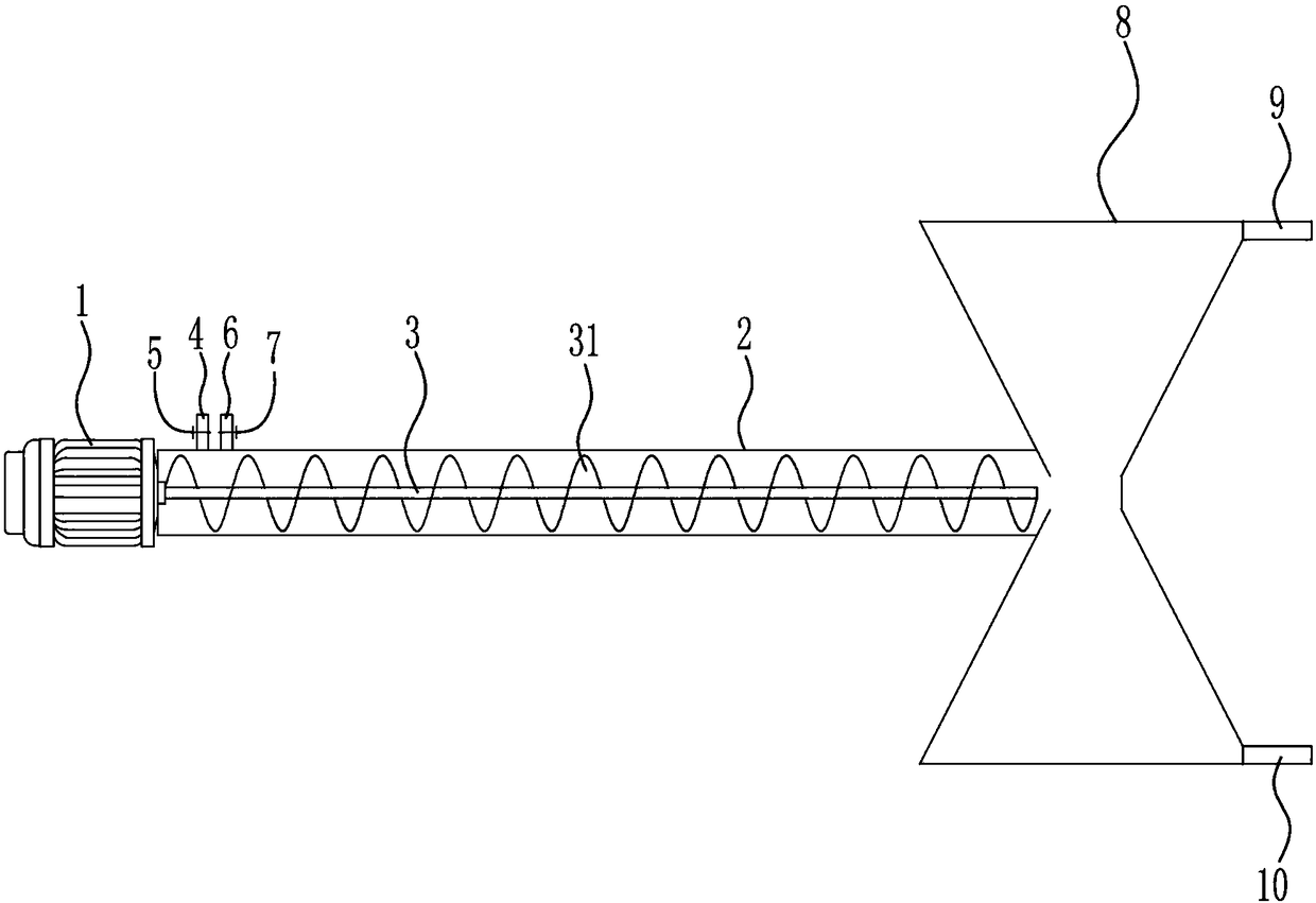
[0023] This embodiment is an extraction device for the separation of rare earth elements, such as figure 1 as shown, figure 1 It is a structural schematic diagram of this specific embodiment; the extraction device includes a motor 1, a mixing transmission pipe 2, a mixing transmission shaft 3, an inlet pipe I4, a valve I5, an inlet pipe II6, a valve II7, a liquid separation box 8, and a liquid outlet Pipe I9 and liquid outlet pipe II10; the left end of the mixing transmission pipe 2 is f...


PUM


Abstract

The invention discloses an extraction device for separating rare earth elements. The extraction device includes a motor, a mixing and conveying pipe, a mixing and conveying shaft, a liquid inlet pipeI, a valve I, a liquid inlet pipe II, a valve II and the like; the motor is fixed to the left end of the mixing and conveying pipe, an output shaft of the motor stretches into the mixing and conveyingpipe and is connected with the mixing and conveying shaft, helical mixing blades are arranged on the mixing and conveying shaft, the left side of the mixing and conveying pipe is connected with the liquid inlet pipe I and the liquid inlet pipe II separately, the valve I is arranged on the liquid inlet pipe I, and the valve II is arranged on the liquid inlet pipe II. The extraction device for separating the rare earth elements is simple in structure, high in practicability and low in operation cost; when rare earth ions are separated through the extraction device, extraction time can be accurately controlled on the basis of fully ensuring that two phases are mixed uniformly, therefore, the extraction efficiency and the separation efficiency are improved to the maximum degree, and then different rare earth ions are efficiently separated.

Description

technical field [0001] The invention relates to an extraction device, in particular to an extraction device for separating rare earth elements. Background technique [0002] Rare earth elements are known as "industrial vitamins" and have become an extremely important strategic resource. Rare earth elements refer to 15 lanthanide elements with atomic numbers from 57 to 71 in the periodic table of elements, and lanthanide elements with similar chemical properties. There are 17 elements including scandium and yttrium. Rare earth elements have been widely used in petroleum, chemical industry, metallurgy, textile, ceramics, glass, permanent magnet materials and other fields. With the advancement of science and technology and continuous breakthroughs in application technology, rare earth elements and The value of its oxide will increase. [0003] At present, the separation of different rare earth ions is usually achieved by extraction, but the properties of various rare earth ion...

Claims


Application Information

Patent Timeline
Patent Type & Authority Applications(China)
IPC IPC(8): C22B3/02C22B3/26C22B59/00
CPCC22B3/02C22B59/00C22B3/26Y02P10/20
Inventor 张浩郭芸逄启寿
Owner JIANGXI UNIV OF SCI & TECH
Learn More