
Predictive control-based permanent magnet synchronous motor composite current control system and method

A permanent magnet synchronous motor and current prediction technology, applied in the field of control, can solve the problems of system control performance degradation, inability to realize current tracking control, and limited application

Active Publication Date: 2018-08-07
QINGDAO UNIV
View PDF3 Cites 11 Cited by
  • Summary
  • Abstract
  • Description
  • Claims
  • Application Information

AI Technical Summary

Problems solved by technology

[0006] However, the design of the deadbeat predictive controller relies on the mathematical model of the motor. When there are disturbances such as parameter changes in the system, the control performance of the system will be severely degraded, and accurate current tracking control cannot be achieved, which limits its application in the electric drive system. application

Method used

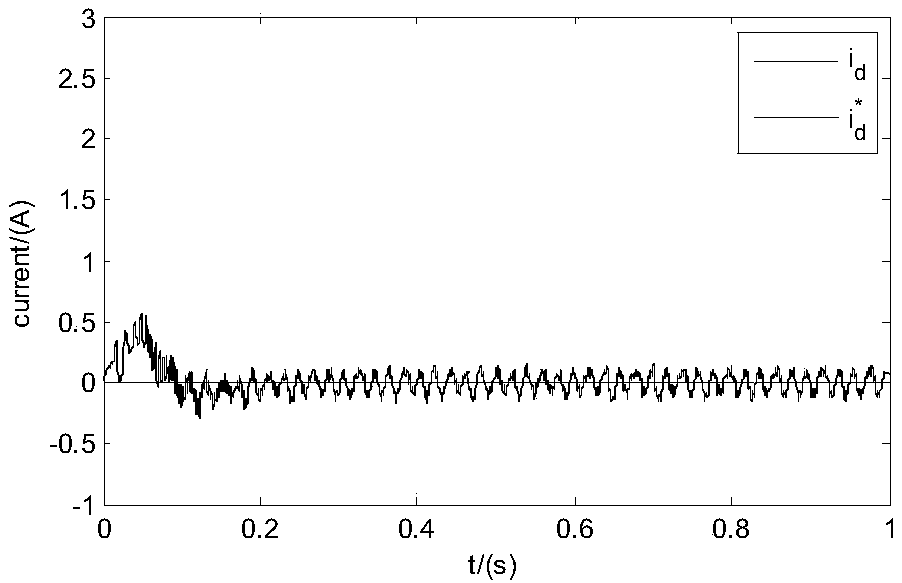
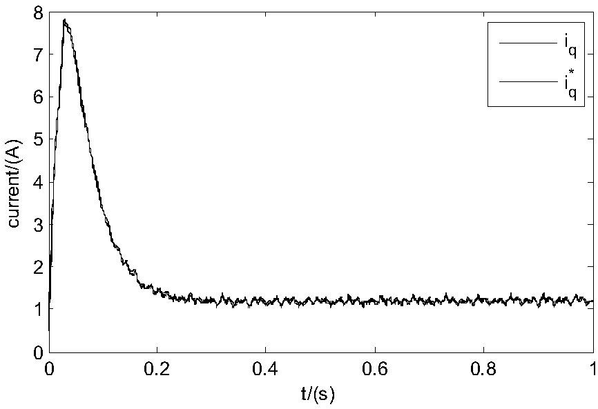

Image

  • Predictive control-based permanent magnet synchronous motor composite current control system and method
  • Predictive control-based permanent magnet synchronous motor composite current control system and method
  • Predictive control-based permanent magnet synchronous motor composite current control system and method

Examples


Embodiment Construction

[0091] It should be pointed out that the following detailed description is exemplary and intended to provide further explanation to the present application. Unless defined otherwise, all technical and scientific terms used herein have the same meaning as commonly understood by one of ordinary skill in the art to which this application belongs.

[0092] It should be noted that the terminology used here is only for describing specific implementations, and is not intended to limit the exemplary implementations according to the present application. As used herein, unless the context clearly dictates otherwise, the singular is intended to include the plural, and it should also be understood that when the terms "comprising" and / or "comprising" are used in this specification, they mean There are features, steps, operations, means, components and / or combinations thereof.

[0093] In a typical implementation of the present application, such as figure 1 As shown, it is a block diagram...


PUM


Abstract

The invention discloses a predictive control-based permanent magnet synchronous motor composite current control system and method. According to the system and method of the invention, the actual angular speed omega of a motor and the given reference rotational speed omegar of the motor, adopted as variables, are inputted to a PI rotational speed loop control module; the PI rotational speed loop control module calculates the difference of the actual angular speed and the reference rotational speed; by means of the proportional plus integral action of a rotational speed loop, the output currenti<*>q of the module is adopted as a q-axis reference current value; the three-phase output current of the motor is subjected to Clark transformation, the current of the motor in a two-phase stationaryalphabeta coordinate system is obtained, and the current is subjected to Park coordinate transformation, so that two-phase current under a dq rotating coordinate system is obtained; and reference current under a motor dq coordinate system and the two-phase current under the dq rotating coordinate system are inputted to a predictive current controller. According to the system and method of the invention, deadbeat predictive control and equivalent interference input are adopted. The current controller of the method can be applied to a PMSM torque or rotational speed driving system, has high current tracking performance and can quickly adjust the system when the system is subject to disturbance, so that the system will not be affected by a variety of disturbance factors.

Description

technical field [0001] The invention relates to the field of control technology, in particular to a compound current control system and method for a permanent magnet synchronous motor based on predictive control. Background technique [0002] Permanent magnet synchronous motors are widely used in electric vehicle drive systems due to their advantages of high efficiency, high power density and high reliability. [0003] The permanent magnet synchronous motor is a kind of multivariable, strongly coupled nonlinear system. Therefore, in the permanent magnet synchronous motor drive system, the vector control strategy according to the orientation of the rotor magnetic field is usually adopted to realize the control decoupling of the speed and current. The outer loop is The speed ring, the inner ring is the current ring. [0004] In practical applications, the control method based on PI is mostly used, and the speed and current tracking control of the motor are realized by adjusti...

Claims


Application Information

Patent Timeline
Patent Type & Authority Applications(China)
IPC IPC(8): H02P21/22H02P21/14
CPCH02P21/14H02P21/22
Inventor 刘旭东于海生于金鹏
Owner QINGDAO UNIV
Learn More