
Signal compensation circuit of medical remote monitoring system

A technology of remote monitoring system and compensation circuit, applied in transmission systems, signal transmission systems, electrical components, etc., and can solve problems such as attenuation

Active Publication Date: 2018-08-03
上海柯渡医学科技股份有限公司
View PDF6 Cites 5 Cited by
  • Summary
  • Abstract
  • Description
  • Claims
  • Application Information

AI Technical Summary

Problems solved by technology

[0003] The current medical remote monitoring system has a lot of data transmission, coupled with the interference of various mobile device signals in the hospital, various interference signals will appear during signal transmission, and attenuation will also occur, so it is necessary to use stable signals at the same time The method of compensating the signal overcomes the signal attenuation phenomenon caused by various consumption of the signal during transmission

Method used


Image

  • Signal compensation circuit of medical remote monitoring system
  • Signal compensation circuit of medical remote monitoring system

Examples


Embodiment 1

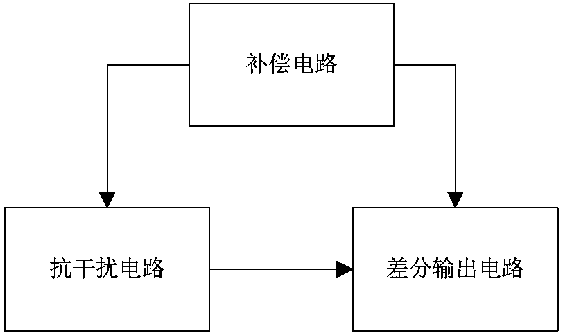
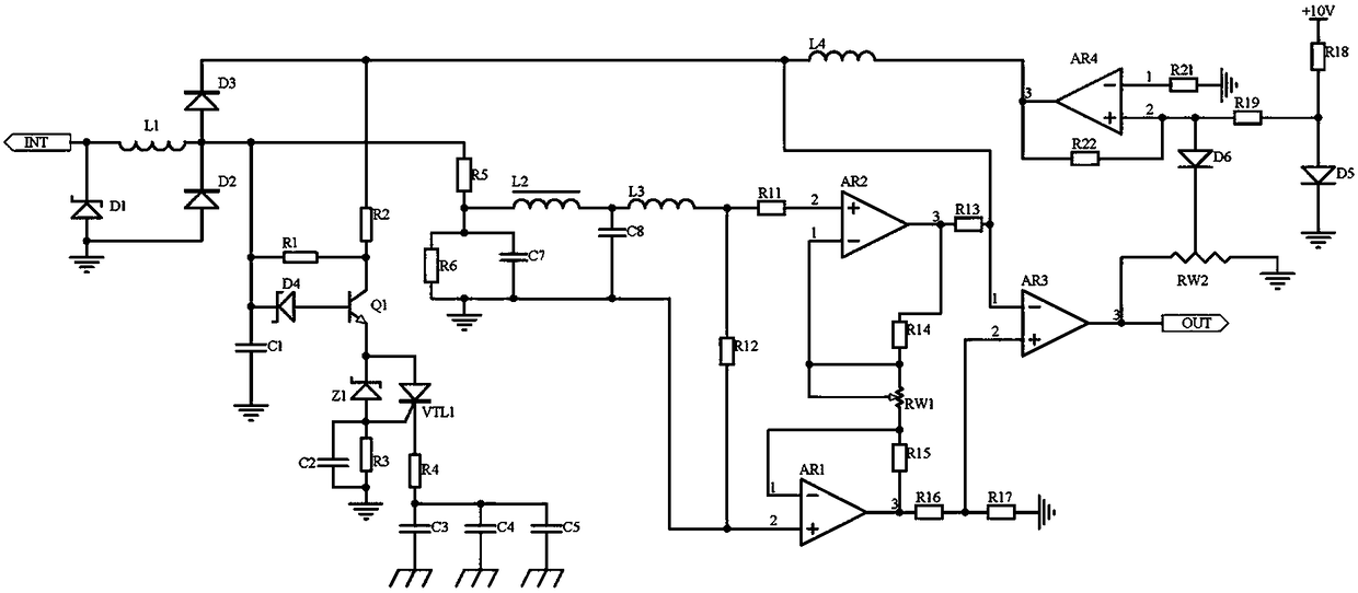
[0014] Embodiment 1, the signal compensation circuit of the medical remote monitoring system includes an anti-jamming circuit, a compensation circuit and a differential output circuit, and the anti-jamming circuit receives signals in the signal transmission channel of the medical remote monitoring system (including pulses collected by corresponding sensors, Human physiological information such as blood pressure, heart rate, the specific acquisition process of the sensor is the prior art, and will not be described in detail here), and the transient pulse signal is suppressed by the transient suppression circuit composed of the inductor L1, the transient suppression diode D1 and the diodes D2 and D3. , to prevent the transient pulse signal from damaging the circuit, and to avoid interference between the signals. At the same time, the diode D4, the transistor Q1, the voltage regulator transistor Z1 and the thyristor VTL1 are used to form a composite circuit to filter out the interf...

Embodiment 2

[0016] Embodiment 2, on the basis of Embodiment 1, the differential output circuit is used to perform differential balance amplification processing on the signal output by the anti-interference circuit, so that the stable signal of a single frequency is not affected by temperature drift and common mode interference Amplification, including the use of operational amplifier AR1, operational amplifier AR2 and operational amplifier AR3, wherein operational amplifier AR1, operational amplifier AR2 constitutes a differential amplifier, the circuit structure is symmetrical, in addition to having a high input impedance, it also has a high Common mode rejection performance, the inverting input of the op amp AR1 is connected to the output signal of the anti-jamming circuit through the resistor R12, the non-inverting input of the op amp AR2 is connected to the output signal of the anti-jamming circuit through the resistor R11, the op amp AR1 The non-inverting input terminal is respectivel...


PUM


Abstract

The invention discloses a signal compensation circuit of a medical remote monitoring system. The signal compensation circuit comprises an anti-interference circuit, a compensating circuit and a differential output circuit, wherein the anti-interference circuit receives signals in a signal transmission channel of the medical remote monitoring system, removes interference signals through filtering by a composite circuit consisting of a diode D4, a triode Q1, a voltage stabilizing tube Z1 and a thyristor VTL1, and finally processes and outputs single-frequency stable signals by a frequency-selecting filter circuit consisting of a resistor R5, a resistor R6, a capacitor C7, inductors L2 and L3 and a capacitor C8, and the signals then enter the differential output circuit and are output; the compensating circuit is used for providing stable power supply for the anti-interference circuit, compensating nonlinearity of interference suppressing signals of the anti-interference circuit and providing compensating signals for the output signals of the differential output circuit, so that amount of attenuation in the signal transmission process is further compensated, the signals in the signaltransmission channel of the medical remote monitoring system are effectively stabilized, and the phenomenon of signal attenuation is eliminated with the compensation method.

Description

technical field [0001] The invention relates to the technical field of medical remote monitoring, in particular to a signal compensation circuit of a medical remote monitoring system. Background technique [0002] With the development of science and technology, the level of modern medicine has also entered a new field. The introduction of large-scale medical equipment has made modern medicine enter a new stage. Advanced medical equipment is an important symbol of a hospital's modernization level, and it is also the basic condition for the continuous improvement of medical technology. The complexity of the remote monitoring system for large-scale medical equipment determines that it is impossible for humans to monitor in real time. This will not only waste a lot of human resources, but also make it difficult to give early warning. The remote monitoring solution can easily cluster distributed medical equipment management, early warning, etc. [0003] The current medical remo...

Claims


Application Information

Patent Timeline
IPC IPC(8): G08C25/00H04B15/00
CPCG08C25/00H04B15/00
Inventor 许少辉
Owner 上海柯渡医学科技股份有限公司
Learn More