Microwave receiving and transmitting antenna, control module group, intelligent lamp, and antenna manufacturing method

A technology for transmitting and receiving antennas and control modules, which is applied to antennas, antenna supports/installation devices, lighting devices, etc., can solve the problems of poor product consistency, large space occupation, and difficult processing, and achieve good consistency and small space occupation. , the effect of improving accuracy

Pending Publication Date: 2018-07-31
瑞德探测技术(深圳)有限公司
View PDF0 Cites 0 Cited by
  • Summary
  • Abstract
  • Description
  • Claims
  • Application Information

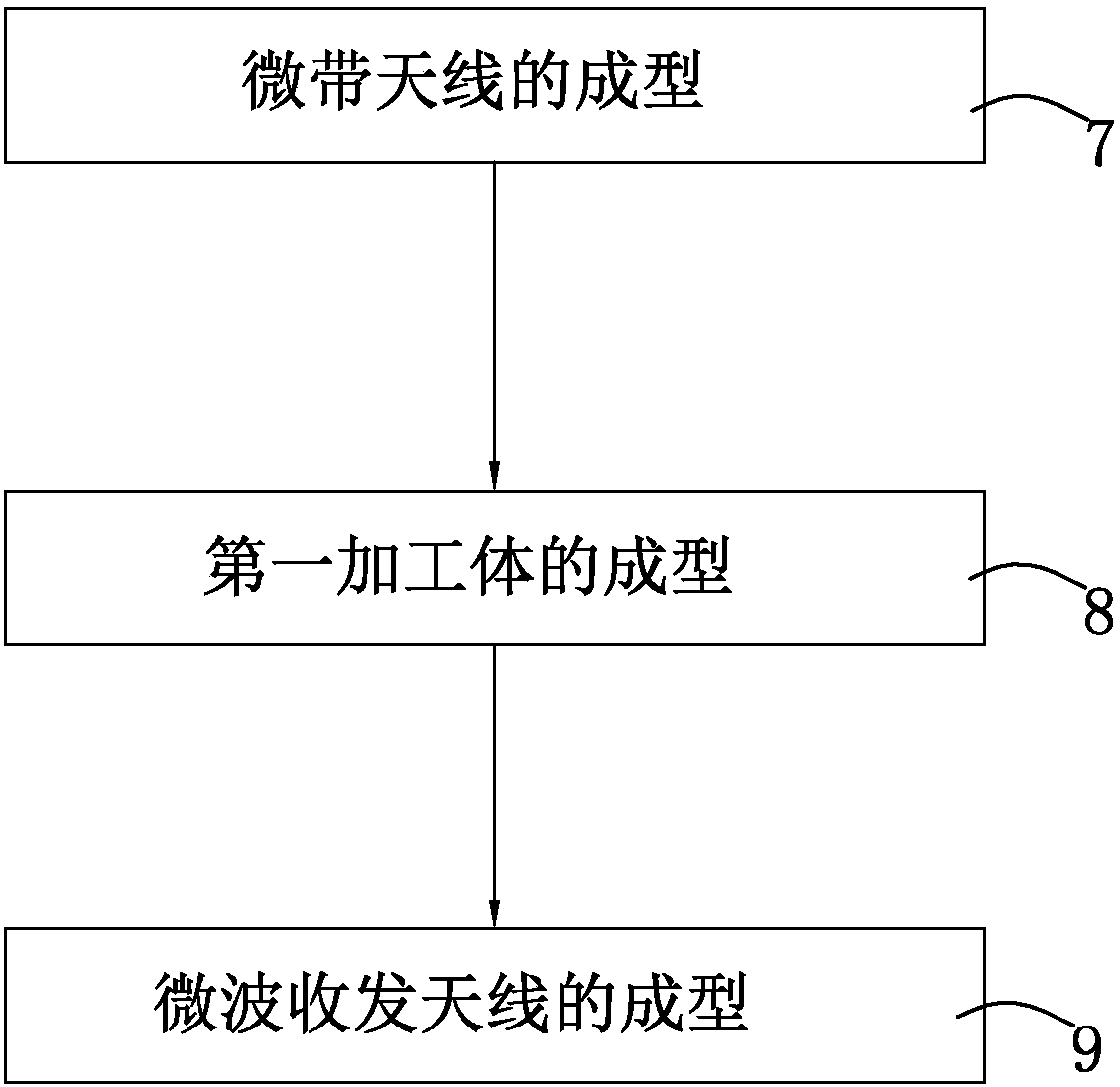
AI Technical Summary

Problems solved by technology

[0003] At present, the working principle of smart lamps is to sense the distance between people and smart lamps through microwave sensing technology to control the on and off of smart lamps. At present, smart lamps generally use microwave transceiver antennas to realize microwave transmission and reception, and then microwave The transceiver antenna feeds back the collected information to the control module, and the control module matches the feedback information with the preset information, and then controls the smart lamps to turn on or off. However, the microwave transceiver antennas currently used in microwave transceiver antennas are generally Pin-type antenna or back-mounted board-type antenna. The pin-type antenna is limited by the structure and has the disadvantage of taking up a lot of space, and the factory needs manual welding during production, resulting in poor product consistency, while the board-type antenna is installed by sticking. There are problems of difficult processing, poor consistency, and easy to fall off

Method used


Image

  • Microwave receiving and transmitting antenna, control module group, intelligent lamp, and antenna manufacturing method
  • Microwave receiving and transmitting antenna, control module group, intelligent lamp, and antenna manufacturing method
  • Microwave receiving and transmitting antenna, control module group, intelligent lamp, and antenna manufacturing method

Examples


Embodiment 1

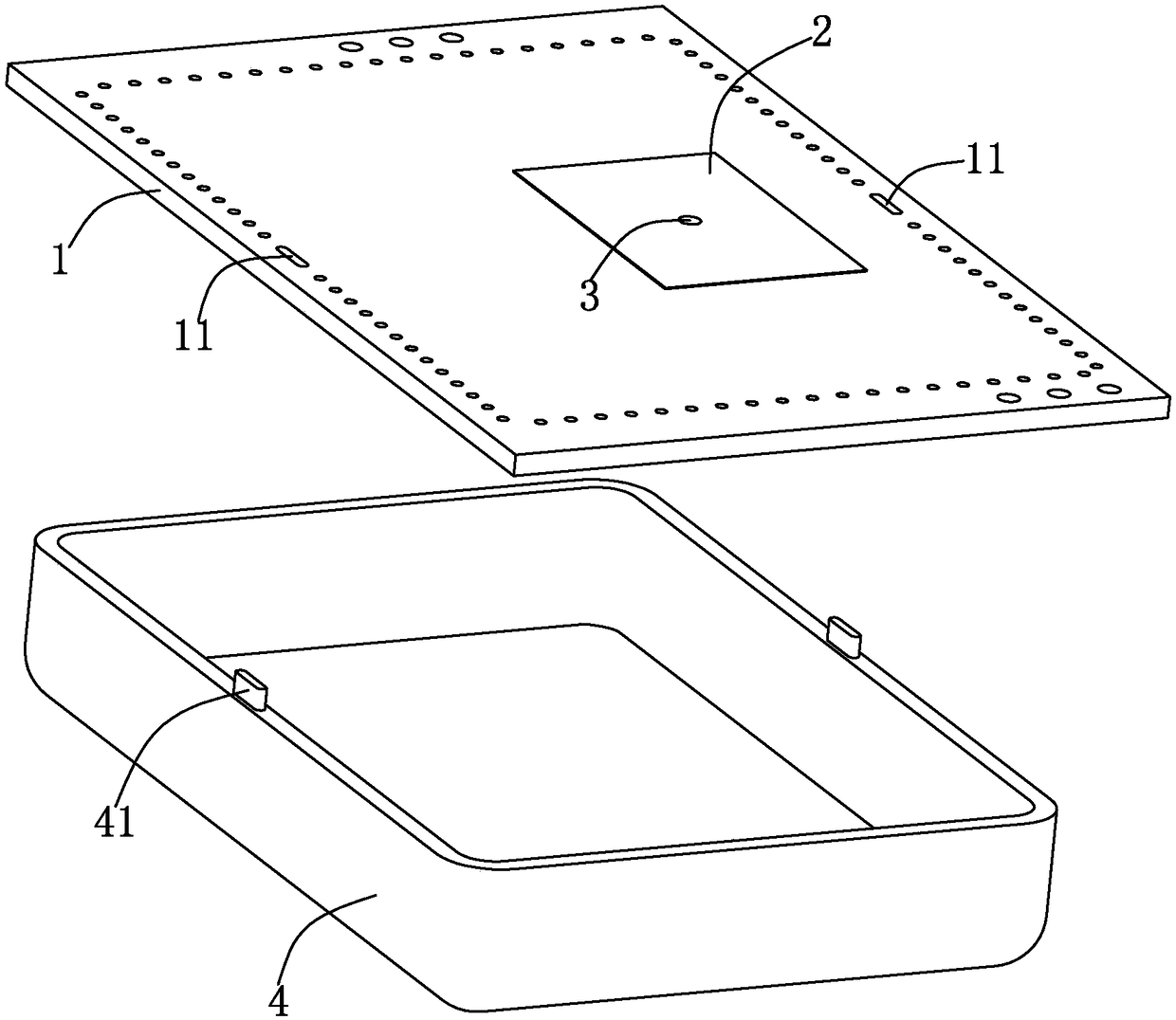
[0042] Microwave transceiver antennas, such as figure 1 As shown, it includes: a first circuit board 1 and a first working circuit arranged on one side of the first circuit board 1, on the first circuit board 1, on the opposite side of the first working circuit, a sheet-shaped micro The strip antenna 2, the microstrip antenna 2 is electrically connected to the first working circuit, wherein the microstrip antenna 2 can be formed by the reserved copper clad inside the first circuit board 2, and does not need to be produced separately, so the production and processing process is more convenient and saves The installation time of the microstrip antenna 2 is reduced, and the cost is reduced. The height of the sheet-shaped microstrip antenna 2 is substantially flush with the surface of the first circuit board 1, thereby having the advantage of occupying a small volume, and the microstrip antenna 2 is arranged on the second circuit board 1. The side opposite to the first working cir...

Embodiment 2

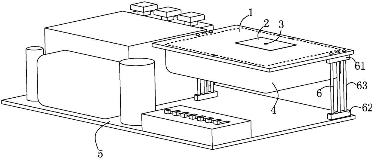
[0054] A control module such as image 3 As shown, it includes a second circuit board 5, a second working circuit arranged on the second circuit board 5, and the microwave transceiver antenna of Embodiment 1, wherein the microwave transceiver antenna is arranged above the second working circuit, and the first The working circuit is arranged close to the second working circuit, and the microwave transceiver antenna is connected to the second circuit board 5 through a group of connectors 6 .

[0055] Wherein, the connector 6 includes: a first socket 61 provided on the first circuit board 1 with a first positioning hole, a second socket 62 provided on the second circuit board 5 with a second positioning hole, and One end is plugged into the first positioning hole and the other end is plugged into the second positioning hole. The connector 6 is respectively connected to the first socket 61 and the second socket on the first circuit board 1 through the pins 63 . The second socket ...

Embodiment 3

[0059] The smart lamp includes the control module of Embodiment 2. By using the above-mentioned control module, the smart lamp can turn on and off the lamp according to the distance between the human body and the lamp. The light fixture is used to install the installation space of the control module.


PUM


Abstract

The invention relates to a microwave receiving and transmitting antenna, a control module group, an intelligent lamp, and an antenna manufacturing method. The microwave receiving and transmitting antenna comprises a first circuit board and a first working circuit disposed on one side surface of the first circuit board. A laminar microstrip antenna is disposed on the first circuit board and is located on an opposite surface of the first working circuit. The microstrip antenna is electrically connected with the first working circuit. Through the advantages that the microstrip antenna is small inoccupied space, is convenient to produce and saves the cost, the control module group and the intelligent lamp which comprise the microwave receiving and transmitting antenna are advantageous in small occupied space and cost saving. Meanwhile, the intelligent lamp also can be enabled to save energy.

Description

technical field [0001] The invention relates to a microwave transceiver antenna, a control module, an intelligent lamp and an antenna manufacturing method. Background technique [0002] With the advancement of science and technology, new smart products are constantly being launched. Among them, smart lamps are a kind of smart products that automatically turn on or off according to the distance between people and smart lamps. It is convenient for people and has a good energy-saving effect. [0003] At present, the working principle of smart lamps is to sense the distance between people and smart lamps through microwave sensing technology to control the on and off of smart lamps. At present, smart lamps generally use microwave transceiver antennas to realize microwave transmission and reception, and then microwave The transceiver antenna feeds back the collected information to the control module, and the control module matches the feedback information with the preset informati...

Claims


Application Information

Patent Timeline
IPC IPC(8): H01Q1/22H01Q13/08H01Q23/00H01Q1/38F21V23/00
CPCH01Q1/22H01Q1/38H01Q13/08H01Q23/00F21V23/003
Inventor 刘剑
Owner 瑞德探测技术(深圳)有限公司
Why Eureka
Try Eureka