Intelligent medical clinical emergency breathing apparatus

A breathing device and emergency technology, applied in the field of medical devices, can solve the problems of inability to control oxygen supply, reduce oxygen efficiency, increase treatment costs, etc., and achieve the effects of meeting special work needs, improving oxygen utilization, and saving treatment costs.

Inactive Publication Date: 2018-07-24
JIAMUSI UNIVERSITY
View PDF7 Cites 0 Cited by
  • Summary
  • Abstract
  • Description
  • Claims
  • Application Information

AI Technical Summary

Problems solved by technology

[0002] At present, during the clinical treatment of internal medicine, patients with some special medical diseases will become difficult to breathe, and may even be in danger of suffocation. The current method for this situation is basically prevented by ventilator, but the current ventilator There is a certain defect in the structure. The patient does not need to use the ventilator under normal conditions, but only in emergency situations. However, the current ventilator structure cannot meet this special requirement. For example, the patent application publication number 201520776197.8 discloses a An emergency breathing device for intelligent internal medicine, but the above patents have certain defects in the use process. First, the patient cannot breathe and cannot consume all the oxygen. Direct discharge reduces the oxygen efficiency in the oxygen tank and increases The cost of treatment, and secondly, it is impossible to control the oxygen supply when the patient exhales. If the supply is too large, the gas flow rate is too high, which may cause discomfort to the patient. If the supply is too small, the treatment effect cannot be achieved. Finally, the device cannot be moved. When oxygen supply is needed, the patient needs to be transferred to the position where the breathing apparatus exists, which is troublesome to operate

Method used


Image

  • Intelligent medical clinical emergency breathing apparatus
  • Intelligent medical clinical emergency breathing apparatus

Examples


Embodiment Construction

[0014] The technical solutions in the embodiments of the present invention will be clearly and completely described below with reference to the accompanying drawings in the embodiments of the present invention. Obviously, the described embodiments are only a part of the embodiments of the present invention, but not all of the embodiments. Based on the embodiments of the present invention, all other embodiments obtained by those of ordinary skill in the art without creative efforts shall fall within the protection scope of the present invention.

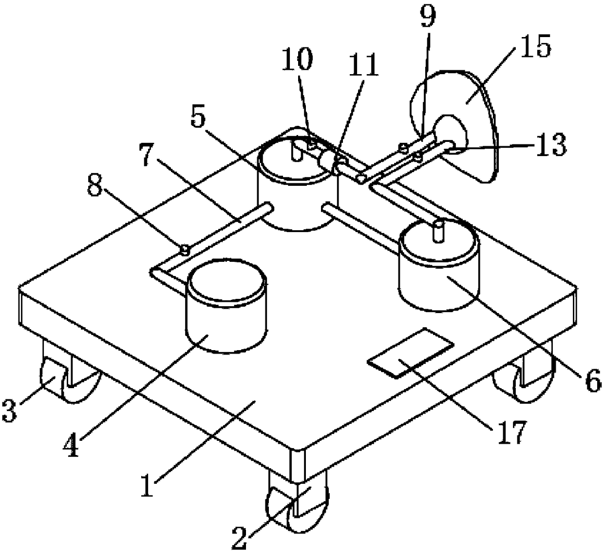
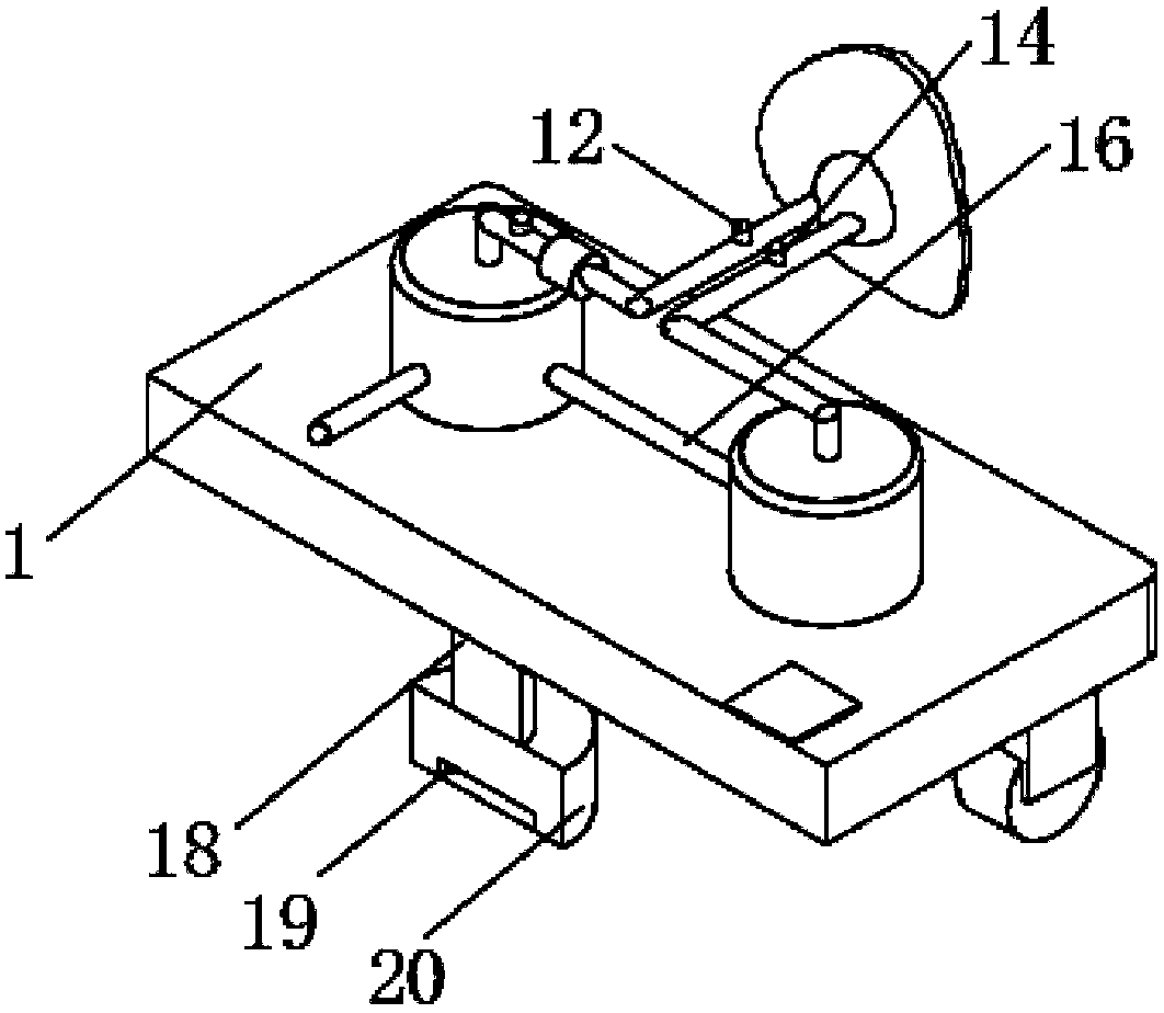
[0015] see Figure 1-2 , the present invention provides a technical solution: an intelligent clinical emergency breathing device for internal medicine, comprising a base 1, the edge of the lower end face of the base 1 is provided with feet 2, the number of the feet 2 is not less than four, and the feet 2 are on the base The edge of the lower end face of 1 is evenly distributed, the lower end of the foot 2 is provided with a roller 3, ...


PUM


Abstract

The invention discloses an intelligent medical clinical emergency breathing apparatus. The breathing apparatus comprises a base, wherein a support leg is arranged at the edge of the lower end surfaceof the base. A roller is arranged at the lower end of the support leg, an oxygen tank, an oxygen compensation tank and a carbon dioxide cleaning tank are arranged on the upper end surface of the base,a gas transmission pipeline I is arranged between the oxygen tank and the oxygen compensation tank, a gas transmission pipeline II is arranged between the oxygen compensation tank and the carbon dioxide cleaning tank, an air suction pipeline is arranged at the upper end of the oxygen compensation tank, A solenoid valve 2, a gas flow measuring instrument and an inhalation valve are sequentially arranged on the suction pipe. The breathing apparatus has the advantages of simple structure and convenient use, which can reuse the oxygen not consumed by the patient, improve the utilization rate of oxygen, and save the treatment cost. The patient's oxygen supply can be adjusted to ensure the patient's comfort and treatment effect, and the apparatus can be moved to meet the special needs of medical workers.

Description

technical field [0001] The invention relates to the technical field of medical devices, in particular to an intelligent clinical emergency breathing device for internal medicine. Background technique [0002] At present, during the clinical treatment of internal medicine, patients will become difficult to breathe under some special medical diseases, and even have the danger of suffocation. There are certain defects in the structure. The patient does not need to use the ventilator under normal conditions, but only in emergency situations. The current ventilator structure cannot meet this special requirement. For example, the patent application publication number 201520776197.8 discloses a Intelligent emergency breathing device in clinical medicine, but the above patents have certain defects in the use process. First of all, the patient cannot breathe and cannot use up the oxygen. The direct discharge reduces the benefit rate of the oxygen in the oxygen tank and increases the ...

Claims


Application Information

Patent Timeline
Patent Type & Authority Applications(China)
IPC IPC(8): A61M16/00
CPCA61M16/0003A61M2016/0033A61M2205/33
Inventor 王春玲李爽李树民
Owner JIAMUSI UNIVERSITY
Why Eureka
Try Eureka