
Piezoelectric flexible sensing device

A sensing device, flexible sensor technology, applied in pressure sensors, sensors, medical science and other directions, can solve the problems of high preparation cost, complex preparation process, complex signal components, etc., to achieve good product stability, simplified preparation process, application Environmentally friendly effect

Inactive Publication Date: 2018-07-24
QINGDAO HUANGHAI UNIV
View PDF14 Cites 9 Cited by
  • Summary
  • Abstract
  • Description
  • Claims
  • Application Information

AI Technical Summary

Problems solved by technology

[0003] At present, most of the existing commercial 3D printing raw materials are powder or filament materials, and the waste of raw materials is serious. However, the price of P(VDF-TrFE) sold in the market is relatively high, so it is necessary to reduce the loss of preparation. Through the transformation of the printing head feeding method Using liquid raw materials as printing materials can save raw materials; (Titterington Don[US]; Wang Patricia[US]; WuBo[US] Inks comprising gallants for 3D printing.US20171564083020170703; French Xavier Boddaert research group reported inkjet printing in 2016 PVDF-TrFE sensor (Haque RI, Vie R, Germainy M, Valbin L, Benaben P, Boddaert X. Inkjet printing of high molecularweight PVDF-TrFE for flexible electronics. Flex Print Electron. 2016; 1(1): 12)), etc.
In terms of analyzing nerve signals, Wang Hong analyzed the whole brain wave to obtain residual limb control information (Human brain-manipulator interface system in micro-power wireless communication mode invented by Wang Hong, Li Chunsheng, Liu Chong, and Zhao Haibin in 2009[P] , the patent number is CN101569569;), but the signal components are complex and the accuracy is affected; we intend to use the signal of the clear residual limb nerve, drawing on the US patent of Hargrove et al. (Hargrove LJ, Simon AM, Young AJ, Lipschutz RD, Finucane SB, Smith DG, et al. Robotic leg control with EMG decoding in anamputee with nerve transfers. N Engl J Med. 2013; 369(13): 1237-42), found that body movements have their own Behavioral patterns, such as the bending of the knee joint, in order to find the signals that control the prosthetics, Hargrove et al. analyzed the EMG signals, and removed the useful signals from the original muscle signals to control the prosthetics (Hargrove LJ, Simon AM, Young AJ, Lipschutz RD, Finucane SB, Smith DG, etal. Robotic leg control with EMG decoding in an amputee with nerve transfers. NEngl J Med.2013; 369(13):1237-42); amputee patients due to their own mobility, lodging and other disabilities There are many certainties, and the method of connecting multiple wires of multiple nerves to the control terminal of the prosthesis is not suitable, so Bluetooth technology is used to wirelessly transmit the myoelectric signals collected in the body to the control terminal of the prosthesis (invented by Chen Peng and Liu Jun in 2016) Prosthesis Surface EMG Signal Acquisition System Based on Wireless Sensor Network [P], Patent No. CN105434088A)
[0004] To sum up, the existing technologies generally suffer from complicated preparation process and high preparation cost. The use of commercial 3D printing raw materials to prepare sensors is a waste of resources and insufficient product stability. Ordinary sensors are susceptible to noise interference by obtaining muscle tension data from the body surface. , skin and other tissues cause signal attenuation and other problems, and the application range is small, the safety is poor, and the service life is short.

Method used


Image

  • Piezoelectric flexible sensing device
  • Piezoelectric flexible sensing device
  • Piezoelectric flexible sensing device

Examples


Embodiment 1

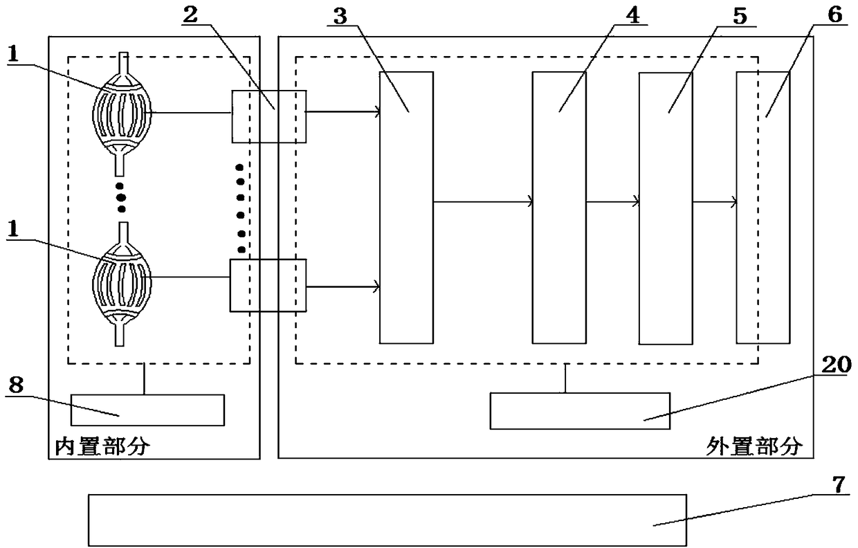
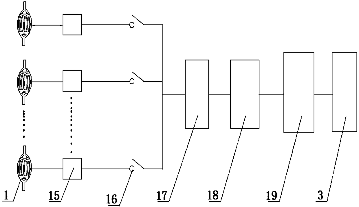
[0035] The piezoelectric flexible sensing device involved in this embodiment is as figure 1As shown, its main structure includes a piezoelectric flexible sensor 1, an EMG signal pre-processing module 2, a Bluetooth wireless transmitting module 3, a Bluetooth wireless receiving module 4, an EMG signal analysis and processing module 5, a prosthetic control module 6, and a charging module 7 , built-in circuit power supply module 8, electrode 9, muscle tissue 10, suture thread 11, preamplifier 15, multi-channel analog switch 16, filter 17 for removing noise interference, post-stage amplifier 18, single-chip microcomputer analog-to-digital conversion unit 19 and prosthesis The power module 20; the piezoelectric flexible sensor device includes a built-in part and an external part, the built-in part is installed on the surface of the residual limb muscle, and the external part is installed in the prosthesis; wherein the piezoelectric flexible sensor 1 of the built-in part is fixed on ...

Embodiment 2

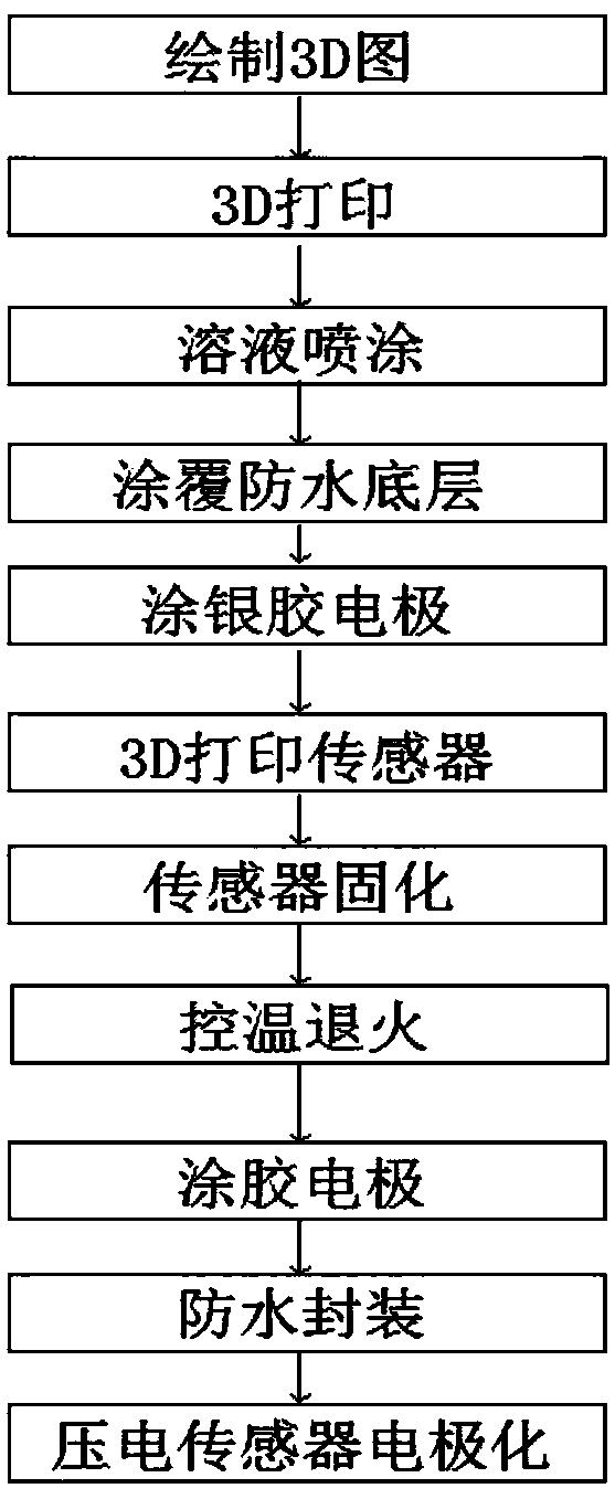
[0039] The preparation method of the piezoelectric flexible sensor involved in this embodiment, its basic process includes the following steps:

[0040] (1) Draw 3D maps: MRI imaging of the muscles of the residual limbs, according to the MRI structure, refer to the standard human anatomical muscle tissue map (such as ZygoteBody (https: / / www.zygotebody.com)), draw the 3D of the corresponding muscles picture;

[0041] (2) 3D printing: Input the muscle 3D model into the 3D printer, and use polylactic acid PLA raw material to 3D print the corresponding muscle model. The printing temperature is controlled between 190 degrees and the heating temperature of the bottom plate is controlled between 60 degrees. According to the standard fusion deposition (FDM) 3D printer process, using the usual filamentary materials to print; smooth the surface of the printed model: in a well-ventilated area, wear non-latex (nitrile or neoprene) gloves to place the model on the bottom In a sealed conta...

Embodiment 3

[0055] This embodiment further explains the process of 3D printing piezoelectric flexible sensor 1: general 3D printing uses wax, powder, filamentary metal or plastic raw materials, and this embodiment uses liquid solution slurry for 3D printing technology; The 3D printing process adopts the printing structure of the mobile bottom plate and the stepping motor drive for a large distance. By adjusting the moving scanning speed and controlling the viscosity and temperature of the slurry, combined with the smallest nozzle of the precision micro-injection pump, the micro-structure printing is realized; the print head part Including the micro-motor controlled needle valve nozzle and stainless steel barrel, the sliding upper end in the stainless steel barrel can be equipped with a chemically inert Teflon piston print push rod, the edge of the Teflon piston is sealed with the stainless steel barrel, and the print head part also includes Heating components and nozzle temperature control...


PUM


Abstract

The invention belongs to the technical field of sensor manufacturing, in particular to a piezoelectric flexible sensing device. The piezoelectric flexible sensing device mainly consists of a piezoelectric flexible sensor, an electromyographic signal preprocessing module, a Bluetooth wireless transmission module, a Bluetooth wireless receiving module, an electromyographic signal analysis processingmodule, a prosthesis motion control module and the like. The piezoelectric flexible sensor collects muscular tension signals and transmits the signals to the electromyographic signal preprocessing module, the electromyographic signal preprocessing module transmits preprocessed electromyographic signals to the electromyographic signal analysis processing module, and the prosthesis motion control module controls the motions of prostheses according to the electromyographic signals processed by the electromyographic signal analysis processing module. The device is reasonable in structure, scientific and reliable in principle, great in product stability, high in sensitivity and capable of greatly improving the life of the disable. By adopting built-in sensors, epidermal tissue can be avoided to directly apply the electromyographic signals, the signals can be more effectively and accurately collected to help manipulation of the prostheses, and therefore the movement functions of the prostheses can be more equivalent to those of original limbs.

Description

Technical field: [0001] The invention belongs to the technical field of sensor production, and specifically relates to a piezoelectric flexible sensing device, which uses a piezoelectric flexible sensor that is 3D printed to seamlessly fit the remaining limb muscles and adjacent tissue shapes to collect muscle tension signals. Working near the optimal working point of the tension state, the sensitivity is higher, relying on the ARM 9 architecture S3C2440 as the core processor of the prosthetic control terminal, through the software intelligent behavior mode to carry out feature recognition and analysis, and separate the control signal of the residual limb from the signal of the missing limb , using the signal of the missing limb to control the movement of the prosthesis through the ARM microcontroller, so that the function of the movement of the prosthesis is close to that of the original limb. Background technique: [0002] There are various types of sensors and their prepa...

Claims


Application Information

Patent Timeline
Patent Type & Authority Applications(China)
IPC IPC(8): A61B5/0488B33Y80/00B33Y70/00B33Y10/00
CPCA61B5/6867A61B5/6885A61B2562/0247A61B2562/12A61B5/389B33Y10/00B33Y70/00B33Y80/00
Inventor 郭海燕吴锜
Owner QINGDAO HUANGHAI UNIV
Learn More