
Gas injection device eliminating sidewind influence and injection method

A blowing device and gas technology, applied in the sintering field, can solve problems such as upward escape, potential safety hazards of personnel poisoning, uneven gas concentration, etc., and achieve the effects of reducing the channel area, improving the sintering effect, and increasing the channel area

Pending Publication Date: 2018-07-10
ZHONGYE-CHANGTIAN INT ENG CO LTD
View PDF19 Cites 1 Cited by
  • Summary
  • Abstract
  • Description
  • Claims
  • Application Information

AI Technical Summary

Problems solved by technology

[0005] The gas injection device in the prior art lacks structural measures that can effectively eliminate the influence of crosswinds, so when the sintering machine workshop is an open workshop, or even an open workshop by the sea, the airflow field in the hood is disturbed by the influence of crosswinds , gas and atmosphere cannot be mixed stably, which will bring the following problems to production:
[0006] 1. The concentration of the gas inhaled into the material layer is uneven: when the airflow field in the hood is disturbed by the influence of the side wind, the gas cannot be mixed stably with the atmosphere in the hood, and it is inevitable that some gas will not be diluted to the design concentration, or some When the gas is diluted below the design concentration, after being sucked into the material layer, the concentration of the gas is different, and the position of combustion and the amount of supplementary heat are also different, which will greatly affect the effect of gas injection assisted sintering Negative impact;
[0007] 2. It is easy to cause gas escape: when the air flow field in the hood is disturbed by the influence of side wind, the flow field in the hood is no longer stable and uniform downward, which will cause the negative pressure on the material surface to be unable to spray the blowing pipe well. The exhaust gas forms a suction force. When the specific gravity of the selected gas (such as coke oven gas) is lighter than the atmosphere, it will inevitably form a situation where part of the gas escapes from the suction force of the material surface and escapes upward.
This will not only cause serious energy waste, but also cause potential safety hazards of personnel poisoning.

Method used


Image

  • Gas injection device eliminating sidewind influence and injection method
  • Gas injection device eliminating sidewind influence and injection method
  • Gas injection device eliminating sidewind influence and injection method

Examples


Embodiment approach

[0057] According to the first embodiment provided by the present invention, a gas injection device for eliminating the influence of side wind is provided.

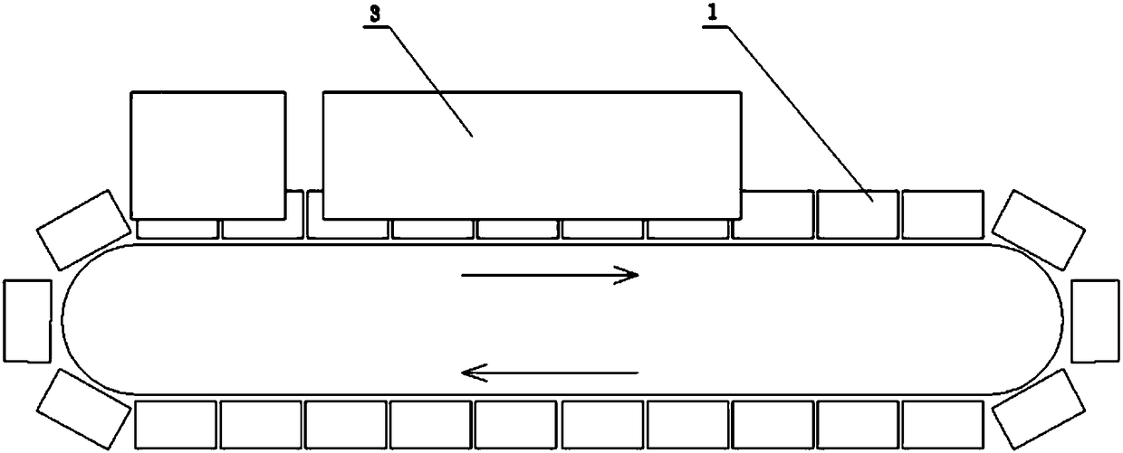
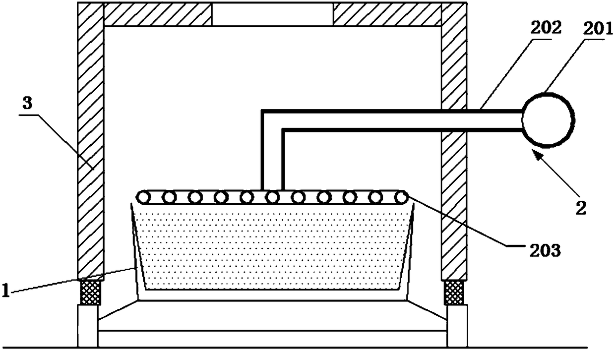
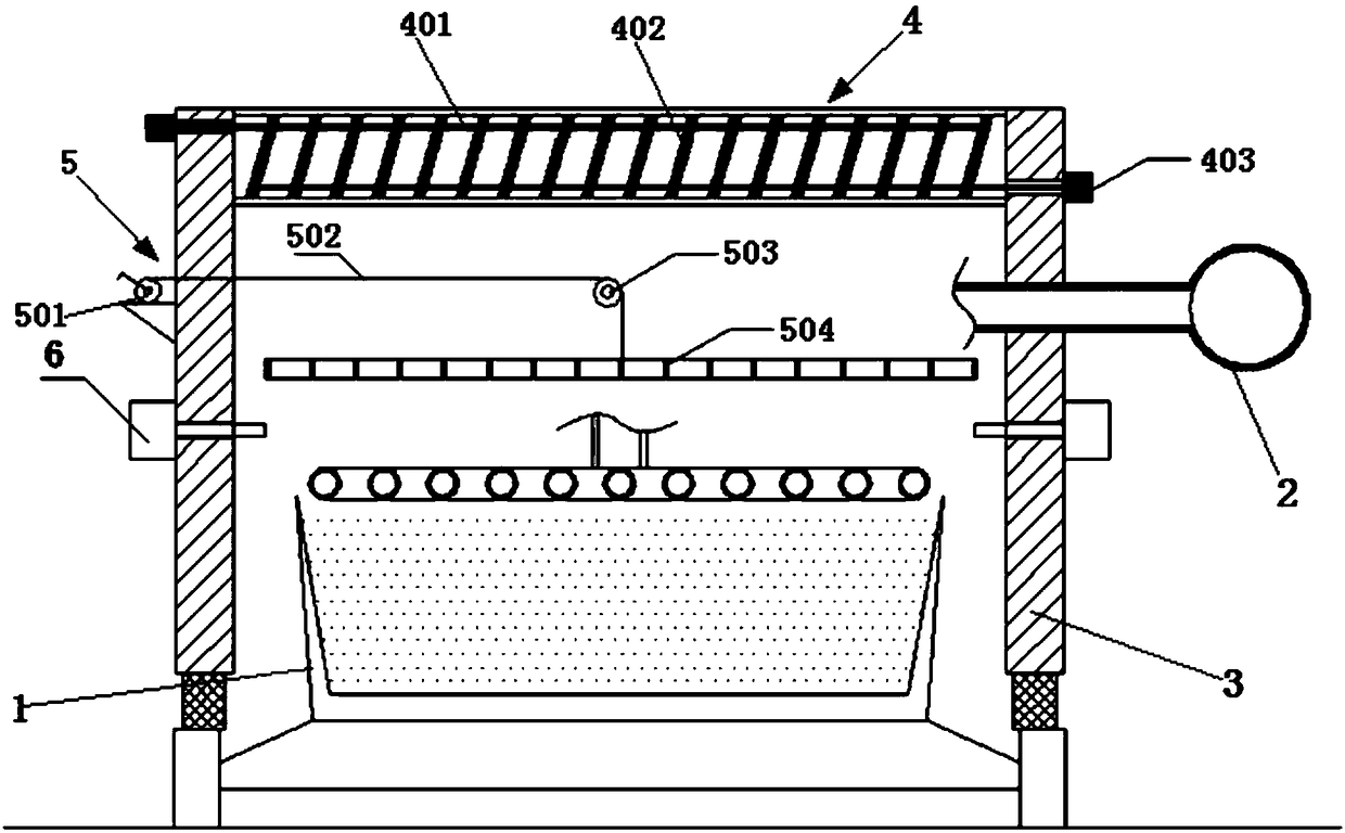
[0058] A gas injection device for eliminating the influence of side wind, the device includes a sintering machine trolley 1, a gas injection device 2, and a spray cover 3. The sintering machine trolley 1 is located in the blowing hood 3 . The gas injection device 2 is located above the trolley 1 of the sintering machine. The two side wall panels of the blowing hood 3 are located on both sides of the sintering machine trolley 1 . The top of the spray cover 3 is a louver type anti-side wind roof device 4 . The louver-type crosswind-proof roof device 4 includes a connecting rod 401 and a louver 402 . One end of the connecting rod 401 protrudes from the side of the spray cover 3 . The louver 402 is connected with the connecting rod 401 .

[0059] In the present invention, the gas injection device 2 includes a gas injectio...

Embodiment 1

[0081] Such as figure 1 As shown, a gas injection device that eliminates the influence of side wind, the device includes a sintering machine trolley 1, a gas injection device 2, and a spray cover 3. The sintering machine trolley 1 is located in the blowing hood 3 . The gas injection device 2 is located above the trolley 1 of the sintering machine. The two side wall panels of the blowing hood 3 are located on both sides of the sintering machine trolley 1 . The top of the spray cover 3 is a louver type anti-side wind roof device 4 . The louver-type crosswind-proof roof device 4 includes a connecting rod 401 and a louver 402 . One end of the connecting rod 401 protrudes from the side of the spray cover 3 . The louver 402 is connected with the connecting rod 401 .

Embodiment 2

[0083] Such as figure 1 As shown, embodiment 1 is repeated, except that the gas injection device 2 includes a gas injection main pipe 201 , a gas injection branch pipe 202 , and a gas injection pipe 203 . The gas injection pipe 203 is arranged above the sintering machine trolley 1 , and the gas injection pipe 203 is located in the injection hood 3 . One end of the gas injection branch pipe 202 is connected to the gas injection main pipe 201 and the other end is connected to the gas injection pipe 203 . The device also includes rectifying means 5 . The rectifying device 5 includes a winch device 501 , a rope 502 , a fixed pulley 503 and a rectifying plate 504 . The capstan device 501 is arranged outside the blowing hood 3 . The fixed pulley 503 is arranged on the bottom surface of the louver type anti-side wind roof device 4 and is located directly above the gas injection pipe 203 . One end of the rope 502 is connected with the winch device 501 , and the other end of the r...


PUM


Abstract

The invention discloses a gas injection device eliminating the sidewind influence. The device comprises a sintering machine trolley, a gas injection device body and an injection cover. The sintering machine trolley is located in the injection cover. The gas injection device body is located above the sintering machine trolley. Two side wallboards of the injection cover are located on the two sidesof the sintering machine trolley. A louver type sidewind-prevention top plate device is arranged at the top of the injection cover and comprises a connecting rod and louver boards. One end of the connecting rod extends out of the side face of the injection cover. The louver boards are connected with the connecting rod. The louver type sidewind-prevention top plate device is arranged at the top ofthe injection cover, by adjusting the louver type sidewind-prevention top plate device, the influence of sidewind on gas injection in a sintering machine is eliminated, and the injection device and acontrol method which can change along with changes of site sidewind conditions and flow field conditions in the cover are developed for achieving the purposes of stable production, smooth production and high yield of a whole production line.

Description

technical field [0001] The invention relates to a gas injection device and an injection method, in particular to a gas injection device and an injection method for eliminating the influence of side wind, and belongs to the field of sintering. Background technique [0002] The sintering process is a key link in the ironmaking process. Its principle is to mix various powdery iron-containing raw materials with an appropriate amount of fuel and flux, add an appropriate amount of water, mix and pelletize the material on the sintering equipment to make the material A series of physical and chemical changes, sintered into blocks, which are sent to the blast furnace for the next step. [0003] In order to reduce the coke ratio and smelting cost of blast furnace ironmaking, blast furnaces often require high strength and high reducibility for sinter. In the sintering process, the sintered ore is generally required to have high strength, high yield, low return rate, and low fuel consu...

Claims


Application Information

Patent Timeline
IPC IPC(8): F27B21/08F27B21/14C22B1/22
CPCF27B21/00C22B1/22F27M2003/04
Inventor 周浩宇刘前王赛辉
Owner ZHONGYE-CHANGTIAN INT ENG CO LTD
Learn More