
Metal bar polishing device

A metal rod and grinding machine technology, which is applied to metal processing equipment, grinding machines, grinding racks, etc., can solve the problems that the surface roughness of metal rods cannot meet the requirements, cannot automatically grind the top and bottom surfaces of metal rods, and cannot be controlled.

Inactive Publication Date: 2018-07-10
广州引航全水科技有限公司
View PDF7 Cites 3 Cited by
  • Summary
  • Abstract
  • Description
  • Claims
  • Application Information

AI Technical Summary

Problems solved by technology

[0002] Before forging, heat treatment or rolling, the metal surface needs to be polished. The main purpose is to remove the oxide layer and burrs on the surface of the metal rod, and to make the roughness of the metal surface meet the specified requirements. When polishing , in addition to the need to control the supply of the grinding machine to change the grinding degree of the metal rod surface due to the process requirements, more importantly, it is necessary to further process the roughness of the metal surface to increase the flatness of the metal surface. In the reference document, the application No.: 201621257624.2, Name: An end grinder for special-shaped pipes and rods, which can only grind the two ends of metal rods, but cannot automatically grind the top and bottom surfaces of metal rods, and does not control the supply of the grinder when grinding amount, the surface roughness of the polished metal rod cannot meet the requirements

Method used


Image

  • Metal bar polishing device
  • Metal bar polishing device

Examples


Embodiment Construction

[0025] The present invention will be further described in detail below in conjunction with the embodiments and the accompanying drawings, but the embodiments of the present invention are not limited thereto.

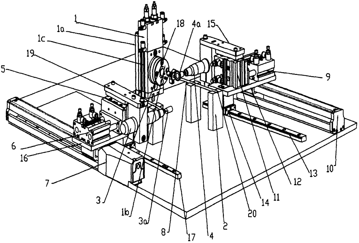
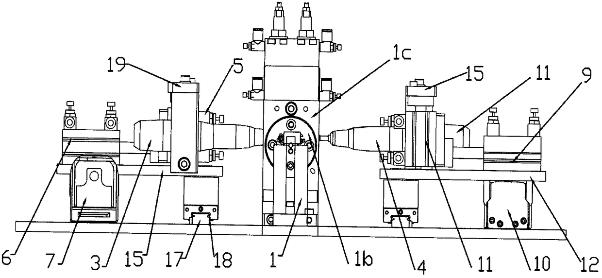
[0026] according to figure 1 as well as figure 2 The shown metal bar grinding device includes a metal bar clamping device 1, a metal bar fixing frame 2 arranged at the front end of the metal bar clamping device 1, a left grinding machine 3 located on the left side of the metal bar clamping device 1, and a The right grinder 4 on the right side of the metal rod clamping device 1; the metal rod clamping device 1 includes a mounting frame 1a, a pneumatic chuck 1b, and a 180-degree rotating cylinder 1c that drives the pneumatic chuck 1b to rotate on the mounting frame 1a , The pneumatic chuck 1b is composed of three chucks distributed at 120 degrees, and its oblique relative movement can clamp the metal rod. The output shaft of the 180-degree rotating cylinder 1c drives th...


PUM


Abstract

The invention discloses a metal bar polishing device which comprises a metal bar clamping device, a metal bar fixing frame, a left polishing machine and a right polishing machine. The metal bar clamping device comprises an installation frame, a pneumatic chuck and a 180-degree rotating air cylinder which drives the pneumatic chuck to rotate on the installation frame. The left polishing machine isfixed to a left lifting frame, the left lifting frame is fixed to an output shaft of a left lifting air cylinder, the left lifting air cylinder is fixed to an output shaft of a left side push air cylinder, the left side push air cylinder is fixed to an output shaft of a left linear actuator, the right polishing machine is fixed to an output shaft of a right side push air cylinder, the right side push air cylinder is fixed to an output shaft of a right linear actuator, the left polishing machine polishes the top face of a metal bar, the right polishing machine polishes the side face of the metal bar, the 180-degree rotating air cylinder enables the bottom face of the metal bar to be upward, and face turning is facilitated for polishing. The structure is simple, the polishing degree can be adjusted, and therefore the surface polishing effect of different metal bars is ensured.

Description

technical field [0001] The invention relates to the technical field of grinding and polishing equipment, in particular to a grinding device for grinding the surface of a metal bar. Background technique [0002] Before forging, heat treatment or rolling, the metal surface needs to be polished. The main purpose is to remove the oxide layer and burrs on the surface of the metal rod, and to make the roughness of the metal surface meet the specified requirements. When polishing , in addition to the need to control the supply of the grinding machine to change the grinding degree of the metal rod surface due to the process requirements, more importantly, it is necessary to further process the roughness of the metal surface to increase the flatness of the metal surface. In the reference document, the application No.: 201621257624.2, Name: An end grinder for special-shaped pipes and rods, which can only grind the two ends of metal rods, but cannot automatically grind the top and bott...

Claims


Application Information

Patent Timeline
Patent Type & Authority Applications(China)
IPC IPC(8): B24B27/00B24B41/06B24B41/02B24B41/00
CPCB24B27/0076B24B41/00B24B41/02B24B41/067
Inventor 卢丽菊
Owner 广州引航全水科技有限公司
Learn More