
Punching die for camshaft bushing

A camshaft and bushing technology, which is applied in the field of mechanical processing, can solve problems such as low production efficiency, high processing cost, and affecting structure, and achieve the effects of improved processing efficiency, reduced processing cost, and accurate punching positioning

Inactive Publication Date: 2018-07-10
江西赣东北轴瓦有限责任公司
View PDF0 Cites 0 Cited by
  • Summary
  • Abstract
  • Description
  • Claims
  • Application Information

AI Technical Summary

Problems solved by technology

There is a round through hole on the side wall of the camshaft bushing. Milling is generally used for the round hole during processing. The clamping speed of the milling process is slow, the processing cost is high, and the overall production efficiency is very low.
The prior art does not use stamping to process the waist hole because of the lack of special processing molds. If a general-purpose machine tool is used for stamping, if the punch is punched from the steel layer of the bushing to the alloy layer, a large number of burrs on the steel layer will be turned over. Alloy, and if punching from the alloy layer of the bushing to the steel layer will cause the deformation of the bushing and affect the structure

Method used


Image

  • Punching die for camshaft bushing
  • Punching die for camshaft bushing
  • Punching die for camshaft bushing

Examples


Embodiment Construction

[0011] A punching die for a camshaft bushing of the present invention will be further described in detail below in conjunction with the accompanying drawings.

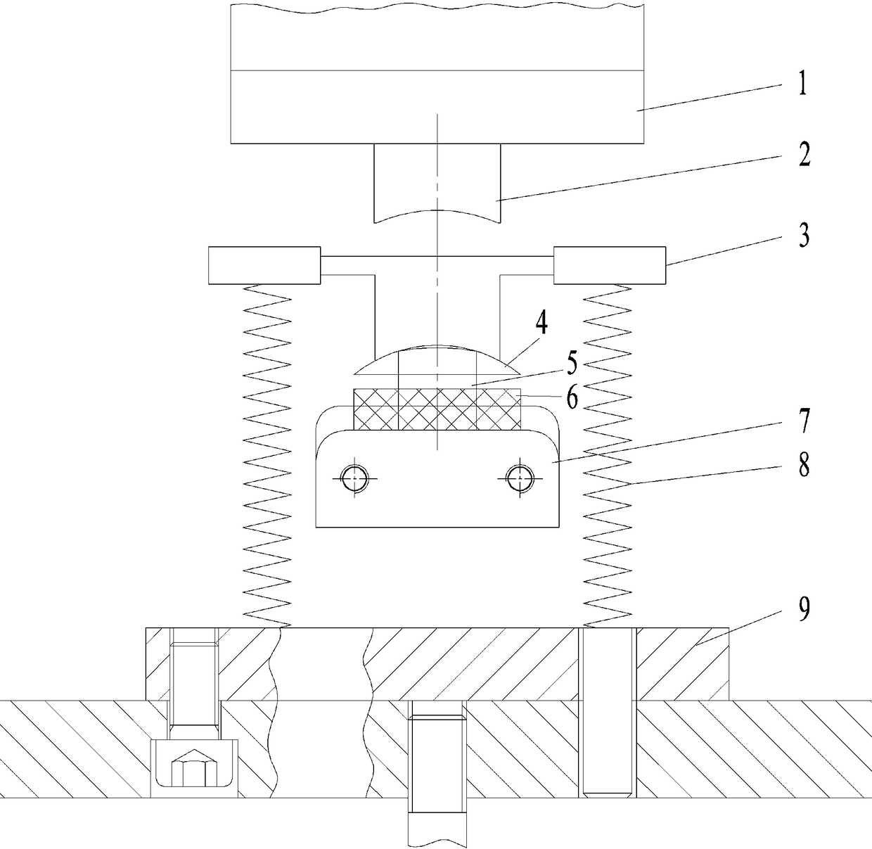
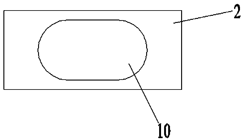
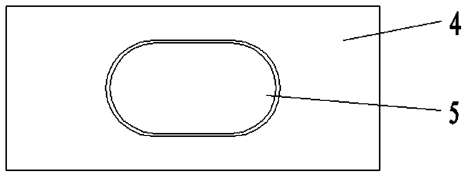
[0012] Figures 1 to 3 The punching die for the camshaft bush shown includes an upper die 2, a lower die, and a reset bracket. The upper die 2 is installed on the machine tool through the connecting plate 1. The bottom of the upper die 2 is set as a rectangular arc surface inwardly. The upper die 2 Waist circular groove 10 is set in the middle part of the arc surface of the bottom, the lower die includes punch 5, stripper plate 4 and punch seat 7, the cross section of punch 5 is set as waist circular, and the bottom waist of punch 5 and upper die 2 is round. The groove 10 is arranged correspondingly, the top surface of the punch 5 is set as an arc surface outward, the top surface of the stripper plate 4 is set as a rectangular arc surface outwardly, and a round through hole is set in the stripper plate 4, and the strip...


PUM


Abstract

The invention discloses a punching die for a camshaft bushing. The punching die comprises an upper punching die body, a lower punching die body and a reset bracket. When the punching die is used, a to-be-machined camshaft bushing is arranged on a punch base in a sleeving mode, the inner surface of the bushing makes contact with the top face of a stripper plate of the lower punching die body, a machine tool is operated to enable the upper punching die body to press, a connecting plate of the upper punching die body presses a top plate of the reset bracket and then drives the stripper plate to fall, therefore, a punch is exposed and makes surface contact with the bushing, and then the upper punching die body continues pressing to enable the punch to cooperate with a kidney-shaped circular groove of the upper punching die body to achieve kidney-shaped circular punching machining. According to the punching die for the camshaft bushing, the problem that a kidney-shaped circular punched holeof the camshaft bushing is difficult to form through punching machining due to the fact that no special die exists is solved, the upper punching die body, the lower punching die body and the reset bracket are arranged, therefore, the camshaft bushing can be fixed and positioned when punching is conducted, punching and positioning are accurate, the machining quality is good, the machining cost ofthe kidney-shaped circular hole is reduced through punching machining, and the machining efficiency is significantly improved compared with milling.

Description

technical field [0001] The invention relates to the technical field of machining, in particular to a punching die for a camshaft bushing. Background technique [0002] The camshaft is a part of the piston engine that is used to control the opening and closing of the valve, and a protective bushing needs to be installed on the outside of the camshaft. There is a round through hole on the side wall of the camshaft bushing. Milling is generally used for the round hole during processing. The clamping speed of the milling process is slow, the processing cost is high, and the overall production efficiency is very low. The prior art does not use stamping to process the waist hole because of the lack of special processing molds. If a general-purpose machine tool is used for stamping, if the punch is punched from the steel layer of the bushing to the alloy layer, a large number of steel layer burrs will be turned over. In the alloy, if the alloy layer of the bushing is punched towar...

Claims


Application Information

Patent Timeline
IPC IPC(8): B21D28/34B21D28/32
CPCB21D28/34B21D28/32
Inventor 周维杰徐汉光
Owner 江西赣东北轴瓦有限责任公司
Learn More