
Wireless remote control igniter

A wireless remote control and igniter technology, which is applied in combustion ignition, lighting and heating equipment, combustion methods, etc., can solve the problems of low safety in use and accidental ignition, and achieve high safety in use, high safety in ignition, and avoid power supply The effect of exhausting damage

Inactive Publication Date: 2018-07-06
曹袁
View PDF15 Cites 0 Cited by
  • Summary
  • Abstract
  • Description
  • Claims
  • Application Information

AI Technical Summary

Problems solved by technology

[0005] In view of this, the object of the present invention is to provide a wireless remote control igniter to solve the technical problems of the existing wireless remote control igniter that may be accidentally ignited due to external strong signal interference and other reasons, and the use safety is low

Method used


Image

  • Wireless remote control igniter
  • Wireless remote control igniter
  • Wireless remote control igniter

Examples


Embodiment 1

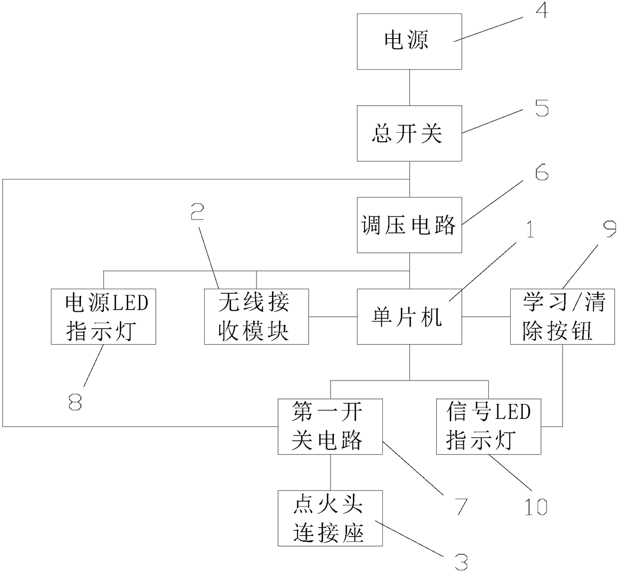
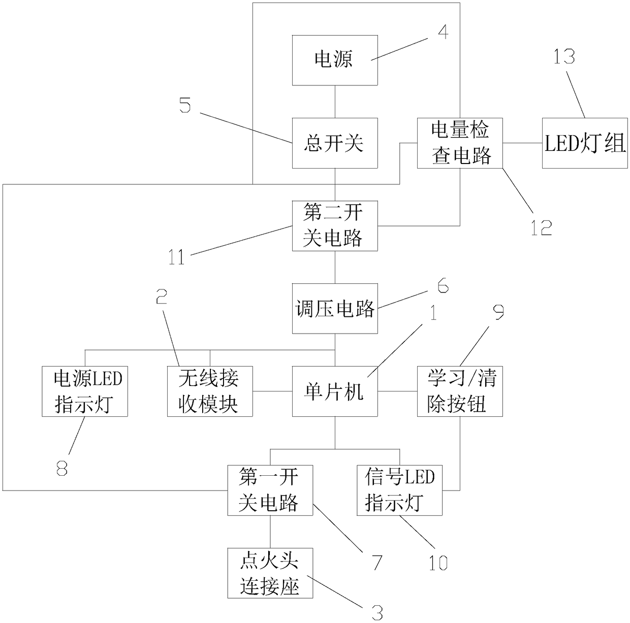
[0030] The wireless remote control igniter of this embodiment includes a single-chip microcomputer 1 , a wireless receiving module 2 connected with the single-chip microcomputer, an ignition head connecting seat 3 , and a power supply 4 . The single-chip microcomputer in this embodiment is STC15F104W; Of course, in different embodiments, said single-chip microcomputer can also be STC89C52 single-chip microcomputer etc.

[0031] The wireless receiving module is an RXB8 superheterodyne type, of course, in different embodiments, the wireless receiving module can also be a 315M / 433M super regenerative wireless receiving module.

[0032] The power supply is connected with the voltage input end of the voltage regulating circuit 6 through the main switch 5, and the voltage output end of the voltage regulating circuit is connected with the voltage input end of the single-chip microcomputer, and the voltage output end of the described voltage regulating circuit is also connected with th...

Embodiment 2

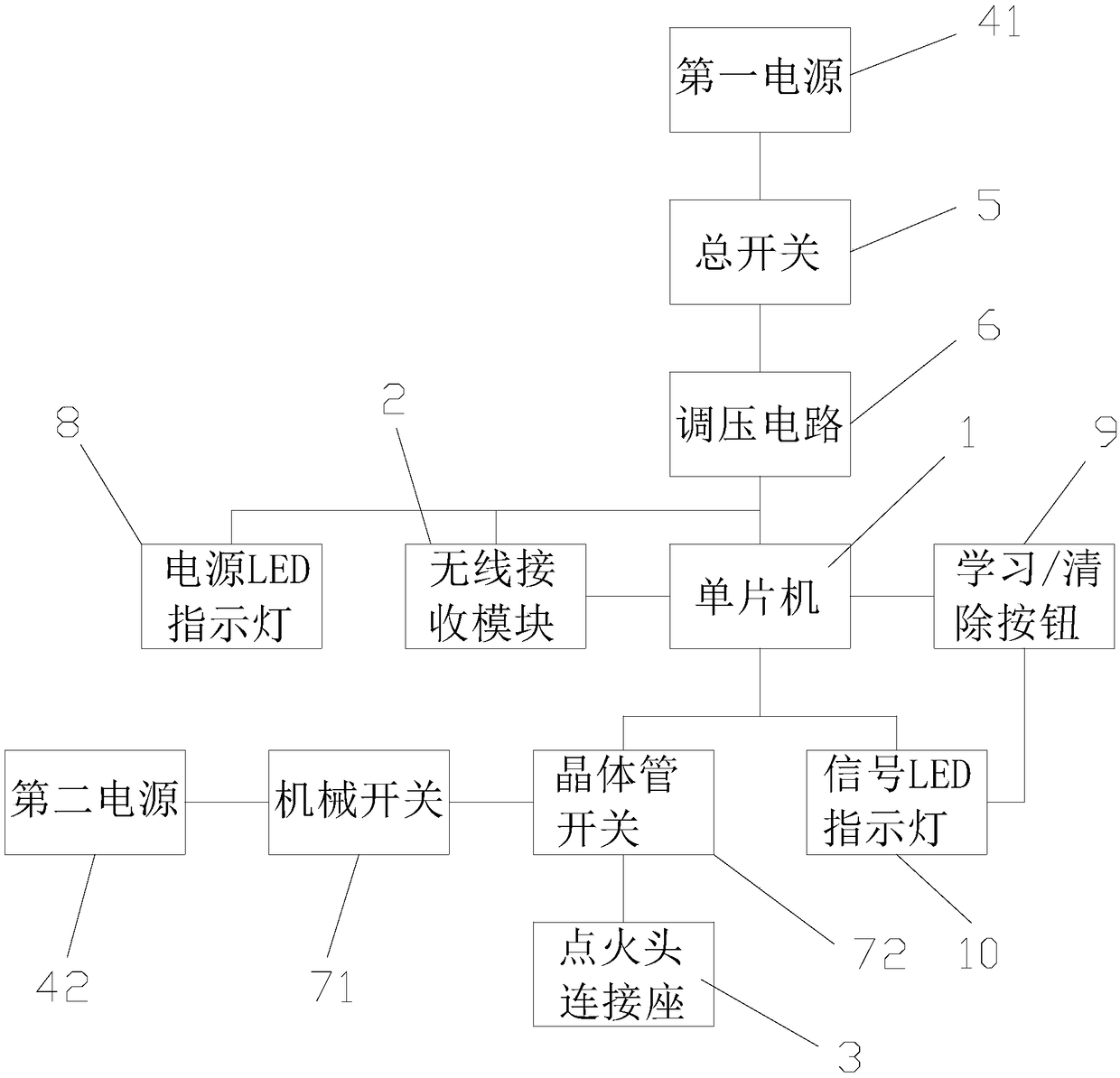
[0051] The wireless remote control igniter of this embodiment includes a single-chip microcomputer 1, a wireless receiving module 2 connected with the single-chip microcomputer, an ignition head connecting seat 3, and a power supply.

[0052] In this embodiment, the power supply is composed of a first power supply 41 and a second power supply 42 that work independently of each other. The first power supply is connected to the voltage input terminal of the voltage regulating circuit 6 through the main switch 5. The second power supply is connected to the second power supply. A switch circuit connection, the first switch circuit is composed of a mechanical switch 71 and a transistor switch 72 switch connection, the second power supply is connected to the transistor switch through a mechanical switch, and the transistor switch is connected to the ignition head connection seat; the transistor The conduction of the switch is controlled by the single chip microcomputer.

[0053] The...


PUM


Abstract

The invention discloses a wireless remote control igniter. The wireless remote control igniter comprises a single-chip microcomputer, a wireless receiving module connected with the single-chip microcomputer, an ignition head connecting base and at least one power source. The wireless receiving module is used for receiving remote control data sent by a remote controller and inputting the remote control data into the single-chip microcomputer. The single-chip microcomputer is used for processing the remote control data input by the wireless receiving module and outputting control signals to a first switch circuit. A delay ignition program is further stored in the single-chip microcomputer. The wireless remote control igniter can solve the problem that when a main switch is turned on, accidental ignition is caused due to foreign strong signal interference, and the ignition safety is higher.

Description

technical field [0001] The invention relates to the technical field of igniters, in particular to a wireless remote control igniter. Background technique [0002] The igniter is used to ignite fuel, and it is widely used in ignition experiments and tests in industries, hazardous chemicals, laboratories, fire protection, public security, military and other fields and departments. [0003] However, in the existing wireless remote control igniter, after the switch is turned on, the problem of accidental ignition may occur due to the interference of strong external signals, and the use safety is relatively low. [0004] Moreover, in the existing wireless remote control igniter, the remote control can store a plurality of remote control data, which does not have the function of preventing false learning, and may be interfered and maliciously operated, resulting in lower safety in use. Contents of the invention [0005] In view of this, the object of the present invention is to...

Claims


Application Information

Patent Timeline
Patent Type & Authority Applications(China)
IPC IPC(8): F23Q21/00
CPCF23Q21/00
Inventor 曹袁王海涛李居耀周建国冉彦杰毛弋刘涛
Owner 曹袁
Learn More