Operating mechanism of ignition switch of lighter
A technology of an ignition switch and an operating mechanism, which is applied in the directions of combustion ignition, igniter with fuel, combustion method, etc., can solve the problems such as the button operation cannot be continuously operated, the ignition of the lighter is unsuccessful, and the button is prone to misoperation, etc. Ignition reliability, avoid accidental ignition, and the effect of not easy to malfunction
- Summary
- Abstract
- Description
- Claims
- Application Information
AI Technical Summary
Problems solved by technology
Method used
Image
Examples
Embodiment 1
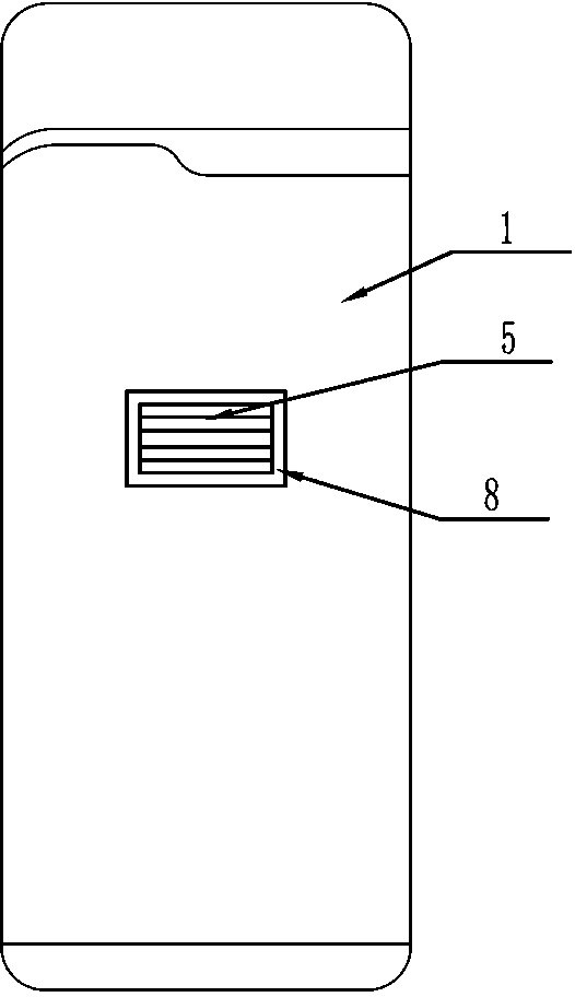
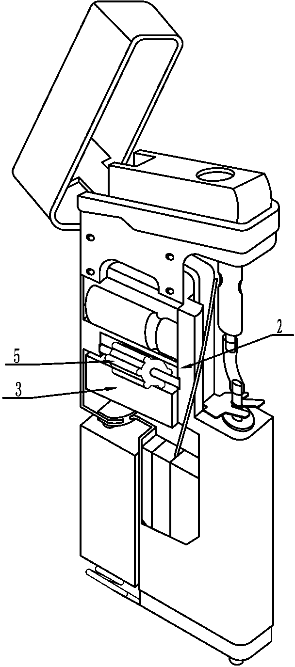
[0031] like figure 1 , figure 2 , image 3 , Figure 4 , Figure 5 , Image 6 , Figure 7 The illustrated embodiment 1 is an operating mechanism for an ignition switch of a lighter, including an ignition switch and an operating mechanism. The ignition switch 3 is provided with a switch contact 4, and the operating mechanism includes a dial 5 installed on the gas tank 2 of the lighter. 5 is placed laterally in the middle of the front of the housing and partly exposed to the housing 1. Several switch contact pressing parts 6 are arranged on the circumference of the dial 5, and the switch contact pressing parts 6 are arranged opposite to the switch contact 4. Part 6 is a bump or a protruding line, and its top is a circular arc transition, which is convenient to slide onto the switch contact 4, and its number can be set according to the usage situation. In this embodiment, there are 6 pieces to improve the reliability of the switching operation. When the dial 5 is turned, a...
Embodiment 2
[0033] like Figure 8 , Figure 9 , Figure 10 , Figure 11 , Figure 12 In the shown embodiment 2, the difference between this embodiment and embodiment 1 is that the installation position of the dial and the position of related components have been adjusted. The dial 5 is vertically placed in the middle of the front of the housing and partially exposed to the housing 1. The layout of the ignition switch and related components has also been adjusted adaptively.
Embodiment 3
[0035] like Figure 13 , Figure 14 , Figure 15 , Figure 16 , Figure 17 As shown in Embodiment 3, the difference between this embodiment and Embodiment 2 is that the installation position of the dial and the position of related components have been adjusted. The dial 5 is vertically placed on the side of the housing and partially exposed to the housing 1. The layout of switches and related components is also adjusted accordingly.
PUM
 Abstract
Description
Claims
Application Information
 - R&D
- Intellectual Property
- Life Sciences
- Materials
- Tech Scout
- Unparalleled Data Quality
- Higher Quality Content
- 60% Fewer Hallucinations
Browse by: Latest US Patents, China's latest patents, Technical Efficacy Thesaurus, Application Domain, Technology Topic, Popular Technical Reports.
© 2025 PatSnap. All rights reserved.Legal|Privacy policy|Modern Slavery Act Transparency Statement|Sitemap|About US| Contact US: help@patsnap.com


