
Tunnelling machine

a tunnelling machine and rock technology, applied in the field of rock tunnelling machines, can solve the problems of high cost, loss of ore from dust, and difficulty in ensuring the safety of the tunnelling machine, and achieve the effect of building up pressur

Inactive Publication Date: 2019-08-20
VAN DYK ANDRE
View PDF4 Cites 0 Cited by
  • Summary
  • Abstract
  • Description
  • Claims
  • Application Information

AI Technical Summary

Benefits of technology

The patent is about a machine that is used to produce a wire mesh lining for tunnel walls and roof. The machine includes a mesh production assembly made up of longitudinal wire spindles and lateral wire spindles, which are fed out and over forming wheels and then urged and welded onto the longitudinal wires by a set of welding rams. Welding operations are done under a water spray to prevent methane gas ignition. The machine also has primary breaking cartridges that are designed to break rock at a specific pressure and depth. An aggregate of small particles is used to fill the hole before the front break cartridge is loaded and the hole is filled with stemming material to provide enough space for the cartridges to fully ignite and build up pressure. Overall, the machine provides a safe and effective way to produce a wire mesh lining for tunnels.

Problems solved by technology

Although this is a well-established method for forming tunnels in rock, it suffers from a number of disadvantages and limitations.
Ore from the dust is lost and the dust needs to be managed, at great cost, for safety reasons.
Using high explosives requires (in some cases) the entire mine to be evacuated or partly evacuated, leading to down time.
Due to the shock waves caused by high explosives other parts of the mine may be caved in or destabilized contributing to the danger of an already a hazardous working environment.
In addition, the highly concentrated ore reefs or veins are blown up together with rock, which dilute the ore extensively.
Tunnelling methods using traditional explosives can, for obvious reasons, not be continuous.

Method used


Image

  • Tunnelling machine
  • Tunnelling machine
  • Tunnelling machine

Examples


Embodiment Construction

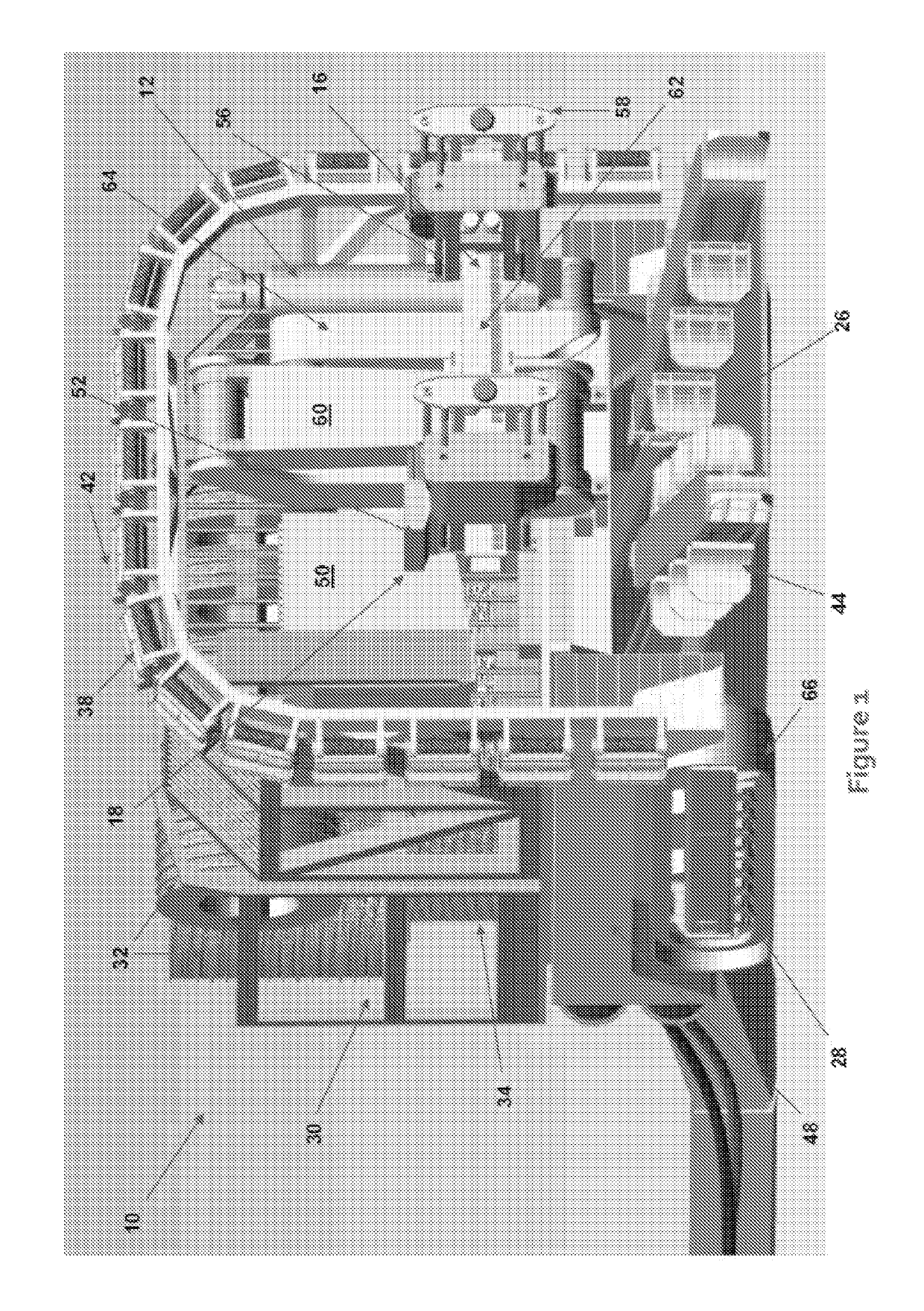
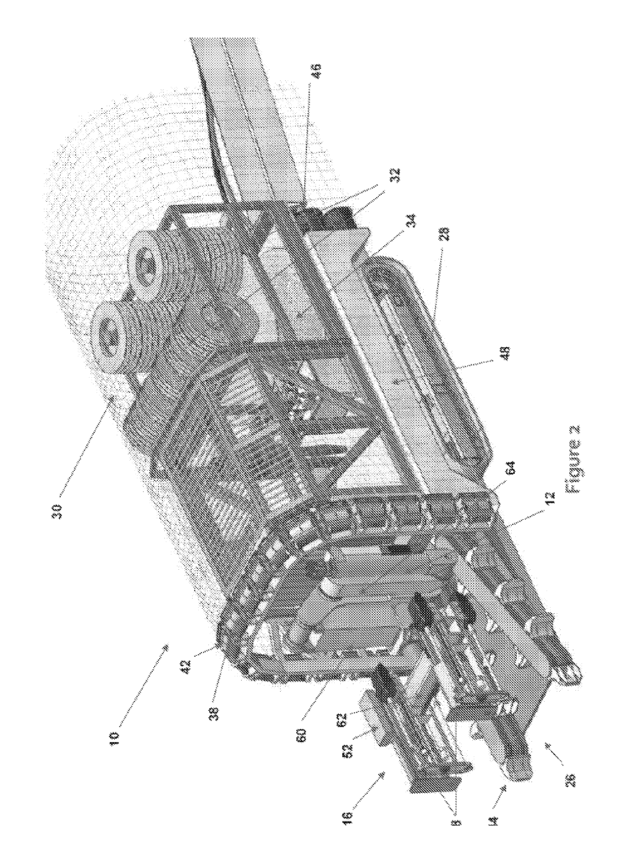
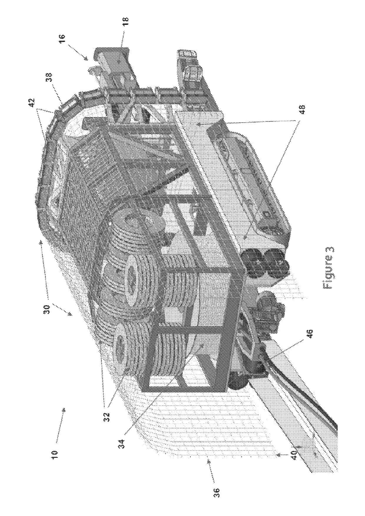
[0006]According to the invention there is provided a machine for tunnelling in rock, which machine includes:

[0007]a pilot drill assembly for drilling a series of interfering parallel holes or a pilot hole into and generally perpendicular into a rock face;

[0008]a blast hole drill assembly for drilling a series of blasting holes around the pilot hole or previous blast hole;

[0009]a charge handling and loading assembly for loading the first series of holes with propellant charges;

[0010]an ignitor system for igniting the charges;

[0011]a rock clearing means for removing the blast rock from the blast face;

[0012]a rock pick for clearing and picking the floor, roof or walls to provide access for the machine into the tunnel;

[0013]a mobility assembly for moving the machine forward; and

[0014]a control console provided with control means for controlling the pilot drill assembly, blast hole drill assembly, charge handling and loading assembly, ignitor system, rock clearing means, and the rock pic...


PUM


Abstract

The invention provides a machine for tunnelling in rock. The machine includes a pilot drill assembly for drilling a series of interfering parallel holes or a pilot hole into and generally perpendicular into a rock face and a blast hole drill assembly for drilling a series of blasting holes around the pilot hole or previous blast hole. The machine further includes a charge handling and loading assembly for loading the first series of holes with propellant charges and an ignitor system for igniting the charges. Included further is a rock clearing means for removing the blast rock from the blast face and a rock pick for clearing and picking the floor, roof or walls to provide access for the machine into the tunnel and a mobility assembly for moving the machine forward. Also included is a control console provided with control means for controlling the pilot drill assembly, blast hole drill assembly, charge handling and loading assembly, ignitor system, rock clearing means, the rock pick, a measure system for gas detection and management, a rock stress measure system and recording system.

Description

TECHNICAL FIELD OF THE INVENTION[0001]This invention relates to a machine for tunnelling in rock.BACKGROUND OF THE INVENTION[0002]The inventor is aware of the use of high explosives to blast break rock to tunnel into rock. Although this is a well-established method for forming tunnels in rock, it suffers from a number of disadvantages and limitations.[0003]Traditional explosives atomise, the rock and ore, in an area with an approximate diameter of up to 100 mm, around and in the vicinity of the drilled hole, from the explosives, including ore such as gold, and create large volumes of toxic dust. Ore from the dust is lost and the dust needs to be managed, at great cost, for safety reasons. Using high explosives requires (in some cases) the entire mine to be evacuated or partly evacuated, leading to down time. Due to the shock waves caused by high explosives other parts of the mine may be caved in or destabilized contributing to the danger of an already a hazardous working environment...

Claims


Application Information

Patent Timeline
Patent Type & Authority Patents(United States)
IPC IPC(8): E21B7/02E21D9/00F42D3/04E21D11/40E21D11/15
CPCE21B7/025E21D9/006F42D3/04E21D11/403E21D11/152
Inventor VAN DYK, ANDRE
Owner VAN DYK ANDRE
Learn More