Steel plate groove cutting equipment

A technology for cutting grooves and steel plates, applied in metal processing equipment, grinding/polishing equipment, grinding slides, etc., can solve the problems of steel slag scratches, weak grinding wheel protection measures, time-consuming and labor-intensive problems, etc.

Pending Publication Date: 2018-06-29
贺欣豪
View PDF9 Cites 3 Cited by
  • Summary
  • Abstract
  • Description
  • Claims
  • Application Information

AI Technical Summary

Problems solved by technology

[0005] In order to overcome the need of the present invention to cut the steel plate when the steel plate is processed, the existing cutting grooves all manually use the grinding wheel to cut the steel plate. The manual use of the grinding wheel to cut the steel plate is not only time-consuming and laborious, but also during work. The protective measures are not strong, and it is easy to be scratched by the steel slag brought up by the grinding wheel. The technical problem to be solved by the present invention is to provide a mechanical instead of manual steel plate cutting groove equipment

Method used


Image

  • Steel plate groove cutting equipment
  • Steel plate groove cutting equipment
  • Steel plate groove cutting equipment

Examples


Embodiment 1

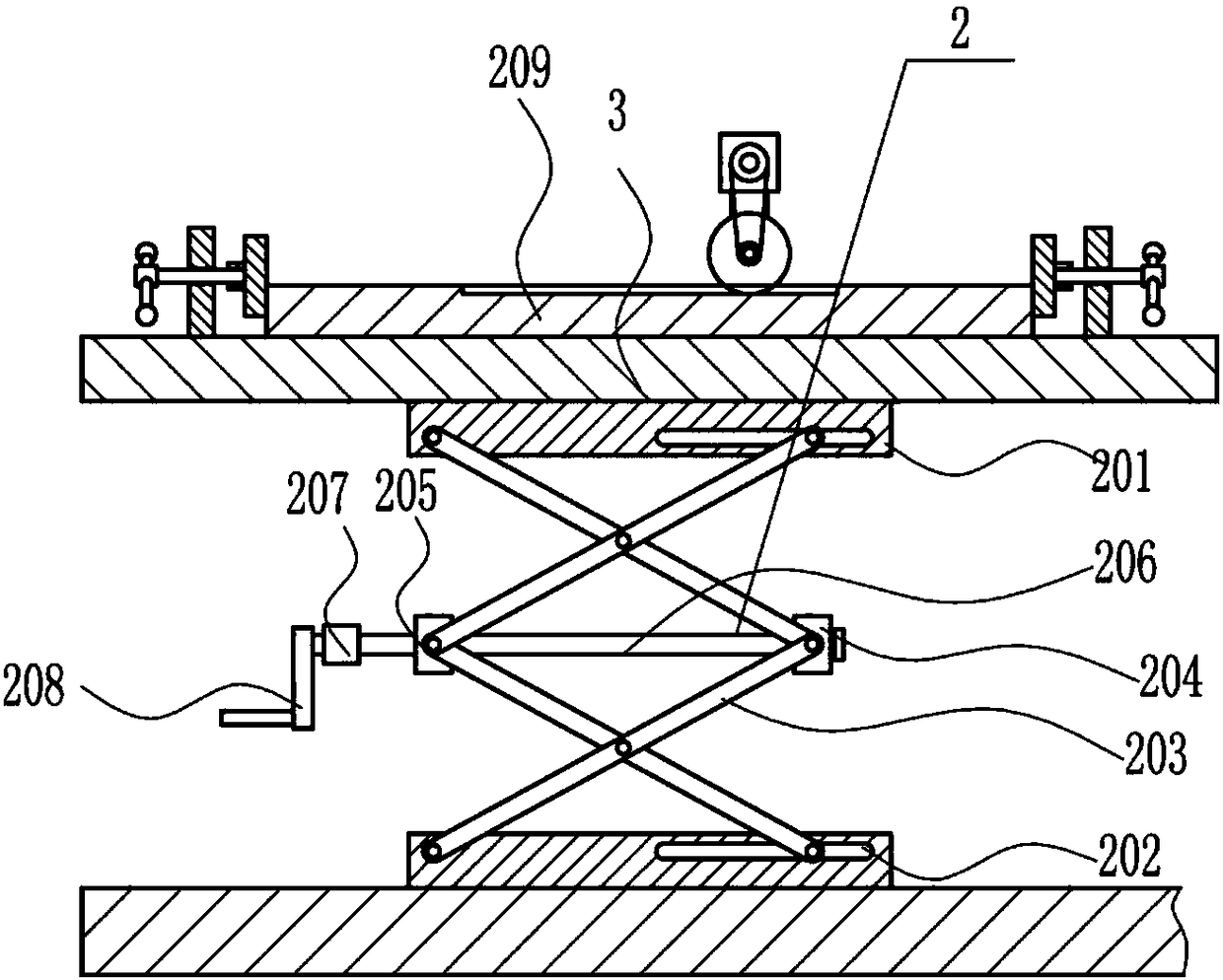
[0033] A steel plate cutting groove equipment, such as Figure 1-7 As shown, it includes a base 1, a lifting device 2, a support plate 3, a clamping device 4, a frame 5, a first bracket 6, a support rib 7, a moving device 8 and a cutting device 9, and a lifting device is provided above the base 1. Device 2, a support plate 3 is provided above the lifting device 2, a clamping device 4 is arranged symmetrically on the left and right sides of the support plate 3, a fixed frame 5 is provided on the upper right side of the base 1, and a frame 5 is fixed above the frame 5. The left side is welded with the first support 6, and one end of the support rib 7 is fixedly connected with the first support 6, and the other end is fixedly connected with the frame 5, and a mobile device 8 is arranged below the first support 6, and at the bottom of the mobile device 8 End is connected with cutting device 9.

Embodiment 2

[0035] A steel plate cutting groove equipment, such as Figure 1-7 As shown, it includes a base 1, a lifting device 2, a support plate 3, a clamping device 4, a frame 5, a first bracket 6, a support rib 7, a moving device 8 and a cutting device 9, and a lifting device is provided above the base 1. Device 2, a support plate 3 is provided above the lifting device 2, a clamping device 4 is arranged symmetrically on the left and right sides of the support plate 3, a fixed frame 5 is provided on the upper right side of the base 1, and a frame 5 is fixed above the frame 5. The left side is welded with the first support 6, and one end of the support rib 7 is fixedly connected with the first support 6, and the other end is fixedly connected with the frame 5, and a mobile device 8 is arranged below the first support 6, and at the bottom of the mobile device 8 End is connected with cutting device 9.

[0036] The lifting device 2 includes a backing plate 201, a scissor lifting frame 203...

Embodiment 3

[0038] A steel plate cutting groove equipment, such as Figure 1-7 As shown, it includes a base 1, a lifting device 2, a support plate 3, a clamping device 4, a frame 5, a first bracket 6, a support rib 7, a moving device 8 and a cutting device 9, and a lifting device is provided above the base 1. Device 2, a support plate 3 is provided above the lifting device 2, a clamping device 4 is arranged symmetrically on the left and right sides of the support plate 3, a fixed frame 5 is provided on the upper right side of the base 1, and a frame 5 is fixed above the frame 5. The left side is welded with the first support 6, and one end of the support rib 7 is fixedly connected with the first support 6, and the other end is fixedly connected with the frame 5, and a mobile device 8 is arranged below the first support 6, and at the bottom of the mobile device 8 End is connected with cutting device 9.

[0039] The lifting device 2 includes a backing plate 201, a scissor lifting frame 203...


PUM


Abstract

The invention relates to cutting equipment, in particular to steel plate groove cutting equipment. Through the steel plate groove cutting equipment, manpower can be replaced with machines. The steel plate groove cutting equipment comprises a base and the like; a lifting device is arranged on the base; a supporting plate is arranged on the lifting device; the left side and the right side of the supporting plate are symmetrically provided with clamping devices; a machine frame is fixed to the right side of the upper portion of the base, and a first bracket is welded to the left side of the upperportion of the machine frame; one end of a supporting rib is fixedly connected with the first bracket, and the other end of the supporting rib is fixedly connected with the machine frame; and a moving device is arranged below the first bracket. The equipment specially applied to steel plate groove cutting is developed. The steel plate groove cutting equipment has the function of being capable ofcutting a lot of steel plates, achieves the effect of quickly cutting the steel plates, and has the characteristics of being convenient to use, safe in using, easy to operate, low in manufacturing cost and the like.

Description

technical field [0001] The invention relates to a cutting device, in particular to a steel plate cutting groove device. Background technique [0002] Cutting is a physical action. Cutting in a narrow sense refers to cutting objects with sharp tools such as knives. Cutting is of great significance in people's production and life. [0003] In the steel plate processing plant, it is necessary to process the steel plate. When the steel plate is processed, the steel plate must be cut. When working, the protective measures of the grinding wheel are not strong, and it is easy to be scratched by the steel slag brought up by the grinding wheel, which seriously endangers the safety of workers. Many workers are unwilling to do such dangerous work, so it is urgent to develop a Machinery replaces manual steel plate cutting groove equipment. Contents of the invention [0004] (1) Technical problems to be solved [0005] In order to overcome the need of the present invention to cut th...

Claims


Application Information

Patent Timeline
Patent Type & Authority Applications(China)
IPC IPC(8): B24B27/06B24B41/02B24B41/06B24B47/12B24B47/04B24B55/02B24B49/00
CPCB24B27/0608B24B41/02B24B41/06B24B47/04B24B47/12B24B49/00B24B55/02
Inventor 贺欣豪刘煜桐雷洪端
Owner 贺欣豪
Why Eureka
Try Eureka