Projection device

A technology of projection device and projection unit, which is applied in projection devices, optics, instruments, etc., and can solve the problem that light cannot be projected on the same plane

Inactive Publication Date: 2012-01-11
COMPAL ELECTRONICS INC
View PDF7 Cites 1 Cited by
  • Summary
  • Abstract
  • Description
  • Claims
  • Application Information

AI Technical Summary

Problems solved by technology

In other words, when a conventional projector is placed on a flat surface, the conventional projector cannot project light onto the same flat surface
Since the projection light path of traditional projectors cannot be changed, there will be more restrictions on applications

Method used


Image

  • Projection device
  • Projection device
  • Projection device

Examples


Embodiment Construction

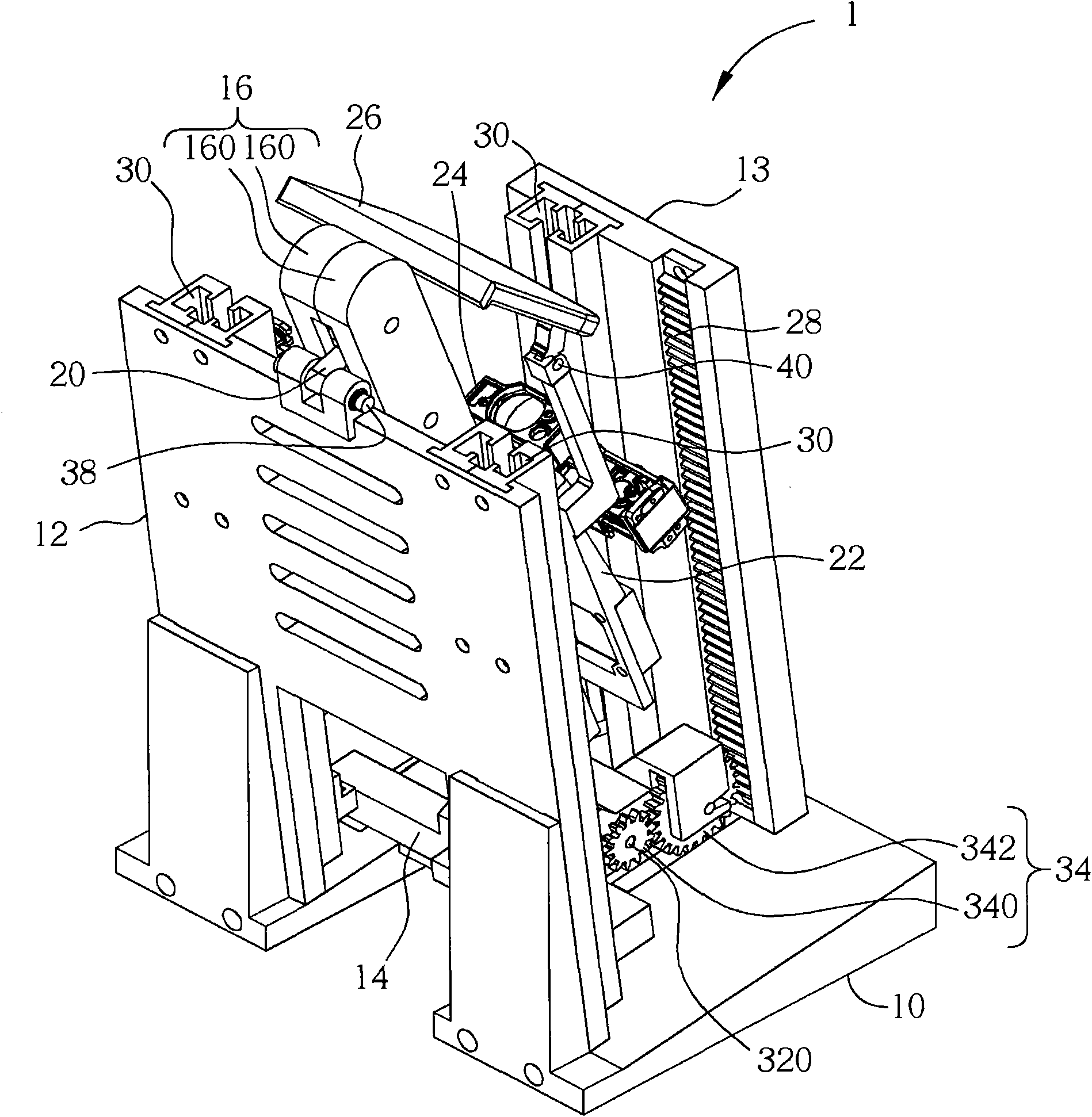
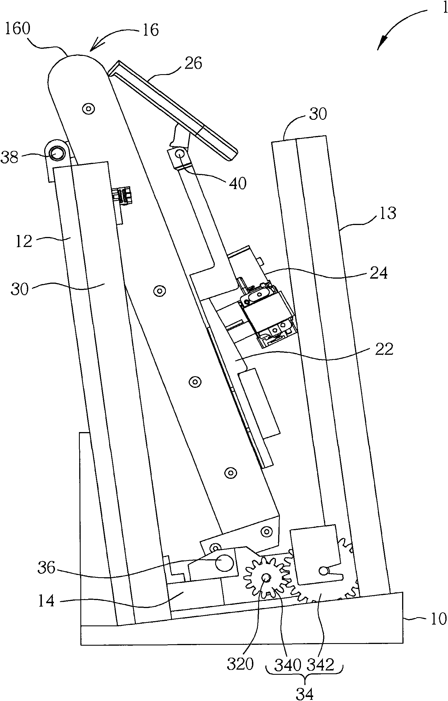
[0019] Please refer to Figure 1 to Figure 5 , figure 1 is a perspective view of the projection device 1 according to an embodiment of the present invention, wherein the second mobile platform 22 is in a retracted position; figure 2 yes figure 1 The side view of the projection device 1 in; image 3 yes figure 1 A perspective view of the projection device 1 in another viewing angle; Figure 4 yes figure 1 A perspective view of the first mobile platform 14 in; Figure 5 yes image 3 The internal view of the transmission member 16 in.

[0020] Such as figure 1 , image 3 and Figure 5 As shown, the projection device 1 includes a base 10, a first side wall 12, a second side wall 13, a first mobile platform 14, a transmission member 16, a transmission belt 18, a first sliding member 20, a The second sliding member 21 , a second moving platform 22 , a projection unit 24 , a mirror 26 , a rack 28 , a plurality of sliding rails 30 , a driving unit 32 and a gear set 34 . B...


PUM


Abstract

The invention discloses a projection device comprising a base, a first side wall, a first mobile platform, a transmission part, a transmission belt, a first sliding part, a second mobile platform and a projection unit. The fist side wall is arranged on the base. The first mobile platform is movably arranged on the first side wall. One end of the transmission part is pivoted to the first mobile platform. The transmission belt is rotatably arranged on the transmission part. One end of the first sliding part is pivoted to the first side wall, while the other end of the first sliding part is movably arranged on the transmission part and fixed on the transmission belt. The second mobile platform is movably arranged on the transmission part and fixed on the transmission belt. The second mobile platform and the first sliding part are arranged oppositely. The projection unit is arranged on the second mobile platform. The projection device provided by the invention has a lifting function and can change the projection light path.

Description

technical field [0001] The invention relates to a projection device, in particular to a projection device which has a lifting function and can change the projection light path. Background technique [0002] In addition to being used for conference reports in general offices, projectors are also often used in various seminars or academic courses due to their audio-visual playback capabilities. Predictably, as the application of projectors becomes more and more extensive, the ways in which projectors are used become more and more diverse. Generally speaking, a conventional projector can only project light onto a projection plane in front of it. In other words, when a conventional projector is placed on a plane, the conventional projector cannot project light onto the same plane. Since the projected ray path of a traditional projector cannot be changed, it is subject to more restrictions in application. Contents of the invention [0003] The object of the present invention...

Claims


Application Information

Patent Timeline
IPC IPC(8): G03B21/14G03B21/28
Inventor 柯信宾赵大庆
Owner COMPAL ELECTRONICS INC
Why Eureka
Try Eureka