Device and method for machining grooves in two sides of inner hole in large end of connecting rod

A technology of connecting rod big end and processing device, which is applied to attachments, electric processing equipment, metal processing equipment, etc., can solve the problem of low efficiency, improve work efficiency, reduce program running coordinate paths, and be suitable for mass production.

Active Publication Date: 2015-12-02
宜都市仝鑫精密锻造有限公司
View PDF7 Cites 2 Cited by
  • Summary
  • Abstract
  • Description
  • Claims
  • Application Information

AI Technical Summary

Problems solved by technology

First cut one side of the inner hole of the connecting rod workpiece, and then move the coordinates to cut the other side of the connecting rod workpiece. After the processing is completed, first disassemble the molybdenum wire, and then remove the connecting rod workpiece. This processing method requires frequent replacement and disassembly of the molybdenum wire. ,low efficiency

Method used


Image

  • Device and method for machining grooves in two sides of inner hole in large end of connecting rod
  • Device and method for machining grooves in two sides of inner hole in large end of connecting rod
  • Device and method for machining grooves in two sides of inner hole in large end of connecting rod

Examples


Embodiment Construction

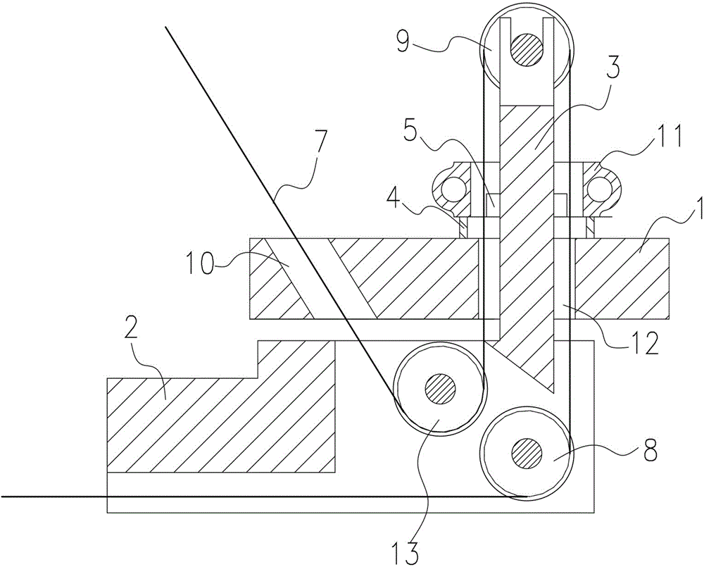
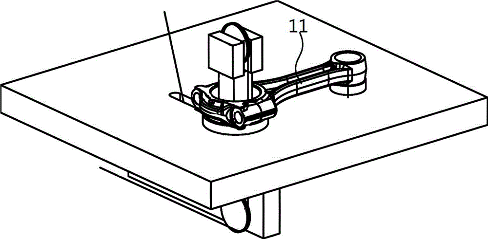
[0022] Such as Figures 1 to 4 As shown: the groove processing device on both sides of the inner hole of the big head of the connecting rod 11, including the worktable 1 and the molybdenum wire 7, the positioning fixture of the connecting rod 11 is fixed on the workbench 1, and the positioning block 2 is arranged under the workbench 1 , a first guide wheel 13 and a second guide wheel 8 are installed on one side of the positioning block 2, and a guide wheel pile 3 is also provided on the positioning block 2, and the guide wheel pile 3 passes through the workbench 1 and the connecting rod for positioning Clamp, one end of which extends to the top of the clamp, and a third guide wheel 9 is installed at the end of the guide wheel pile 3, and the molybdenum wire 7 is installed on the first guide wheel 13, the third guide wheel 9 and the second guide wheel in turn. On round 8.

[0023] Further, a first through hole 10 and a second through hole 12 are provided on the workbench 1 , t...


PUM


Abstract

The invention provides a device and method for machining grooves in the two sides in an inner hole of the large end of a connecting rod. The device comprises a workbench and a molybdenum wire. A connecting rod positioning clamp is fixedly arranged on the workbench. A positioning block is arranged under the workbench. A first guide wheel and a second guide wheel are installed on one side of the positioning block. The positioning block is further provided with a guide wheel pile, the guide wheel pile sequentially penetrates through the workbench and a clamp, one end of the guide wheel pile stretches to the portion above the clamp, a third guide wheel is installed at the end of the guide wheel pile, and the molybdenum wire is sequentially installed on the first guide wheel, the third guide wheel and the second guide wheel. According to device and method for machining the grooves in the two sides of the inner hole in the large end of the connecting rod, the molybdenum wire does not need to be detached or installed.

Description

technical field [0001] The invention relates to a device and a method for processing grooves on both sides of an inner hole of a large head of a connecting rod. Background technique [0002] The processing technology of the connecting rod of the automobile engine requires that before the connecting rod is broken, grooves with a depth of 0.3mm to 0.5mm must be cut on both sides of the inner hole of the big head of the connecting rod. The traditional fixture design needs to install the connecting rod workpiece first, and then the molybdenum wire through the various guide wheels (such as Figure 5 shown), and then run the processing program. First cut one side of the inner hole of the connecting rod workpiece, and then move the coordinates to cut the other side of the connecting rod workpiece. After the processing is completed, first disassemble the molybdenum wire, and then remove the connecting rod workpiece. This processing method requires frequent replacement and disassembl...

Claims


Application Information

Patent Timeline
Patent Type & Authority Applications(China)
IPC IPC(8): B23H7/02B23H7/10B23H11/00
CPCB23H7/02B23H7/105B23H11/003
Inventor 李光全
Owner 宜都市仝鑫精密锻造有限公司
Why Eureka
Try Eureka