
Two-dimensional-control reflecting mirror and control method thereof, and laser scanner including the same

A technology of mirrors and transmitters, applied in the field of laser scanners, can solve the problems of limited deflection angle accuracy, poor stability, and inter-axis interference of mirror control components, achieve control accuracy and scanning laser pointing control accuracy, overcome The effect of poor stability and stable support structure

Active Publication Date: 2018-06-26
SHENZHEN INST OF ADVANCED TECH
View PDF5 Cites 16 Cited by
  • Summary
  • Abstract
  • Description
  • Claims
  • Application Information

AI Technical Summary

Problems solved by technology

[0005] 1. Poor stability and serious interference between axes
When the two piezoelectric ceramics are driven, they have a downward displacement but the fixed support structure does not, which will make the three support points of the bracket unable to maintain a height and cause the mirror to always be in a tilted state and cannot be kept horizontal
This asymmetric support structure has poor stability and serious inter-axis interference. The error caused by this structure cannot be improved by the control algorithm, which limits the deflection angle accuracy of the mirror control part.
[0006] 2. The reflection point is easy to shift
The optical feedback method of this mirror control part is on one side of the mirror. With the different reflection angles of the mirror, the reflection point on the back of the mirror does not remain the same, and may be in the longitudinal direction (parallel to the piezoelectric drive structure) The displacement direction) will produce an offset, which will lead to deviations in the geometric model of the feedback optical path, resulting in poor feedback accuracy. This kind of flaw in principle cannot be solved simply by the control algorithm, and then affects the two-dimensional control mirror. control precision

Method used


Image

  • Two-dimensional-control reflecting mirror and control method thereof, and laser scanner including the same
  • Two-dimensional-control reflecting mirror and control method thereof, and laser scanner including the same
  • Two-dimensional-control reflecting mirror and control method thereof, and laser scanner including the same

Examples


Embodiment Construction

[0039] It should be noted that, in the case of no conflict, the embodiments in the present application and the features in the embodiments can be combined with each other.

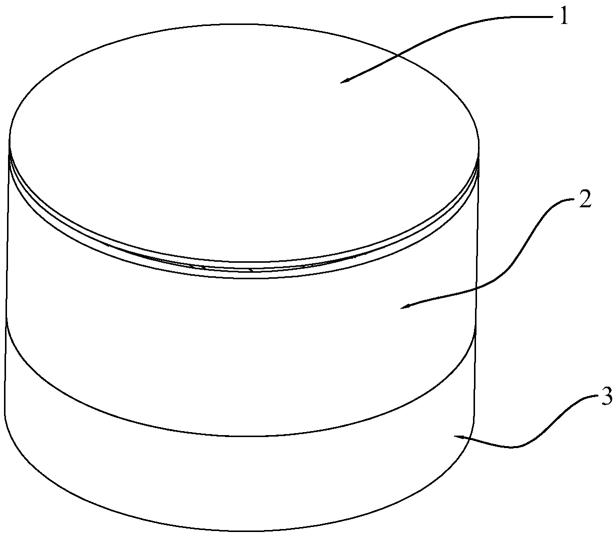
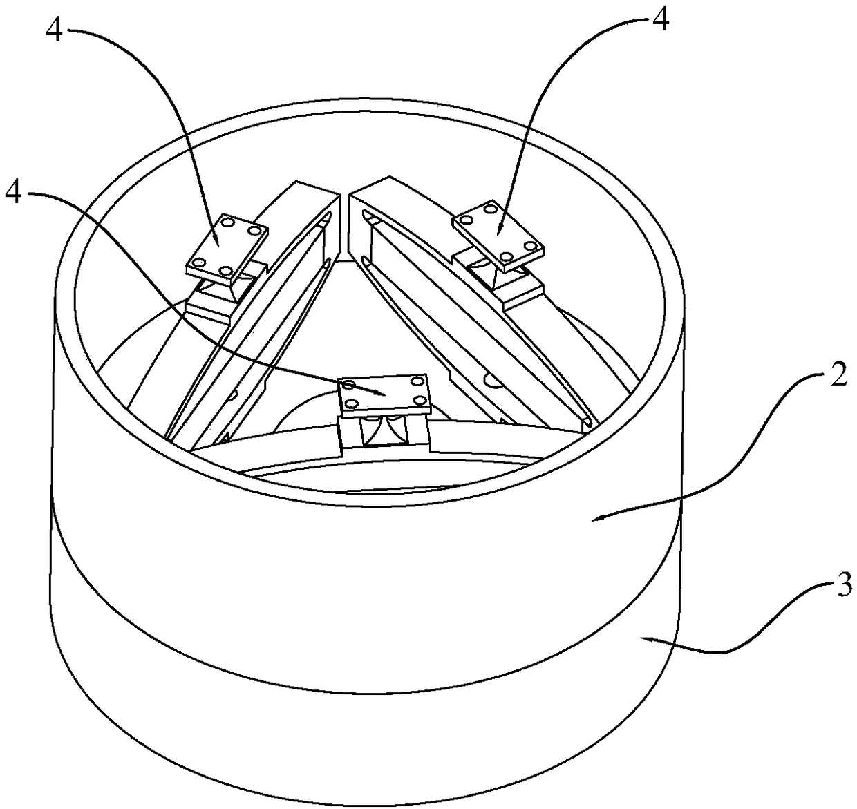
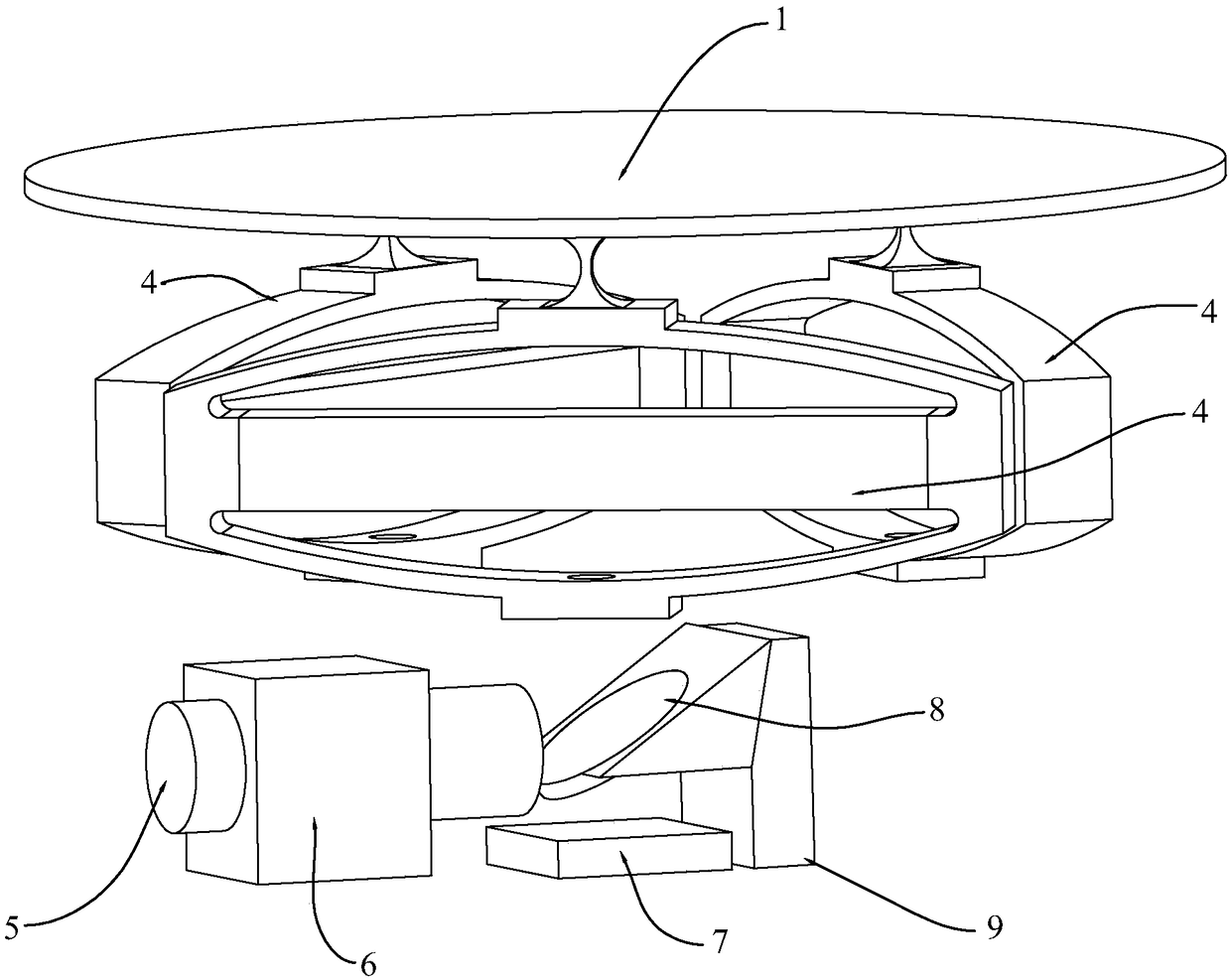
[0040] Figure 1 to Figure 3 They are the schematic diagram of the external structure, the peek view of the internal structure, and the exploded view of the internal structure of the two-dimensional control mirror based on direct optical feedback in this embodiment, respectively. Figure 4 , Figure 5 The feedback optical path structure diagram and the feedback optical path schematic diagram of the two-dimensional control mirror based on direct optical feedback of the present invention are respectively shown.

[0041] refer to Figure 1 to Figure 4 As shown, the present invention is based on a two-dimensional control mirror with direct optical feedback, including a parallel beam emitter 5, a half mirror 8, a mirror 1, a position sensitive detector 7, a closed-loop control circuit and three A piezoelectr...


PUM


Abstract

The invention discloses a two-dimensional-control reflecting mirror and a control method thereof, and a laser scanner including the same. Three piezoelectric driving structures support the reflectingmirror and the supporting points arranged in a positive triangle mode. Problems of poor stability and serious inter-shaft interference of the existing non-symmetric supporting structure of the reflecting mirror in the prior art are solved; and thus the reflecting mirror supporting structure is stabilized, thereby improving the control precision of the two-dimensional-control reflecting mirror. Besides, because of constraining algorithm controlling on the three piezoelectric driving structures, the displacement of the reflection point location in a longitudinal direction during the deflection process of the reflecting mirror becomes zero, so that the stability of the geometric model of the optical feedback path is guaranteed and thus the control precision of the two-dimensional control reflecting mirror and the scanning laser pointing control precision are effectively guaranteed.

Description

technical field [0001] The invention relates to the technical field of optical communication, in particular to a two-dimensional control reflector, a control method thereof and a laser scanner containing the same. Background technique [0002] Laser scanners are widely used in modern cutting-edge industrial production and scientific research. Among them, the laser scanner includes a mirror control component, which is a device that can precisely control the pointing of the laser beam, which can compensate the jitter error of the laser and ensure that the laser beam can be aligned in real time. It is often used in high-precision industrial processing systems, high-energy laser systems, Laser communication systems and imaging systems, etc. [0003] In the prior art, for example, the piezoelectric laser scanner is a new type of laser scanner that uses piezoelectric ceramics as the driving source and a flexible hinge as the transmission mechanism. It has the advantages of compac...

Claims


Application Information

Patent Timeline
IPC IPC(8): G02B26/08G02B26/10G02B7/198
CPCG02B7/198G02B26/0816G02B26/10
Inventor 陈巍徐越张花信刘鹏陈良培焦国华
Owner SHENZHEN INST OF ADVANCED TECH
Learn More