
Parameter optimization method for powder laser 3D (Three-Dimensional) printing forming technology

A technology of process parameters and 3D printing, applied in the direction of design optimization/simulation, electrical digital data processing, special data processing applications, etc., can solve the problems of narrow powder application range, long test cycle, and different performance of molded parts, etc., to achieve applicable The effect of wide range, short test cycle and low test cost

Active Publication Date: 2018-06-22
HANS LASER TECH IND GRP CO LTD +1
View PDF3 Cites 6 Cited by
  • Summary
  • Abstract
  • Description
  • Claims
  • Application Information

AI Technical Summary

Problems solved by technology

[0003] Although 3D printing technology has many technical advantages, choosing the appropriate printing process parameters is the key. Different process parameters have a great impact on the molded parts, such as different scanning speeds, laser powers, and overlapping rates. Similarly, it will indirectly lead to different performances of the molded parts. Inappropriate selection of process parameters will also affect the performance of the parts, such as excessive thermal stress and large thermal deformation, which will lead to molding failure of the parts in severe cases.
The selection of process parameters of traditional 3D printing technology requires process engineers to determine through a large number of process experiments, and there are many process parameters, which leads to long test cycle and high cost, and the process parameters obtained by the test have a narrow scope of application for powder

Method used


Image

  • Parameter optimization method for powder laser 3D (Three-Dimensional) printing forming technology
  • Parameter optimization method for powder laser 3D (Three-Dimensional) printing forming technology
  • Parameter optimization method for powder laser 3D (Three-Dimensional) printing forming technology

Examples


Embodiment Construction

[0048] In order to facilitate the understanding of the present invention, the present invention will be described more fully below with reference to the associated drawings. Preferred embodiments of the invention are shown in the accompanying drawings. However, the present invention can be embodied in many different forms and is not limited to the embodiments described herein. On the contrary, the purpose of providing these embodiments is to make the disclosure of the present invention more thorough and comprehensive.

[0049] It should be noted that when an element is referred to as being “fixed” to another element, it can be directly on the other element or there can also be an intervening element. When an element is referred to as being "connected to" another element, it can be directly connected to the other element or intervening elements may also be present. The terms "vertical," "horizontal," "left," "right," and similar expressions are used herein for purposes of ill...


PUM


Abstract

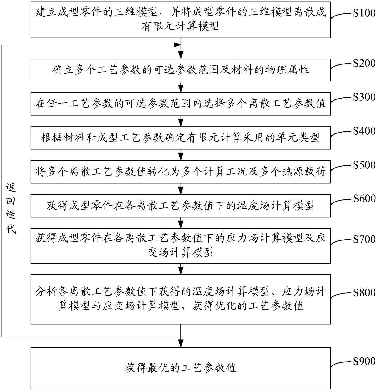
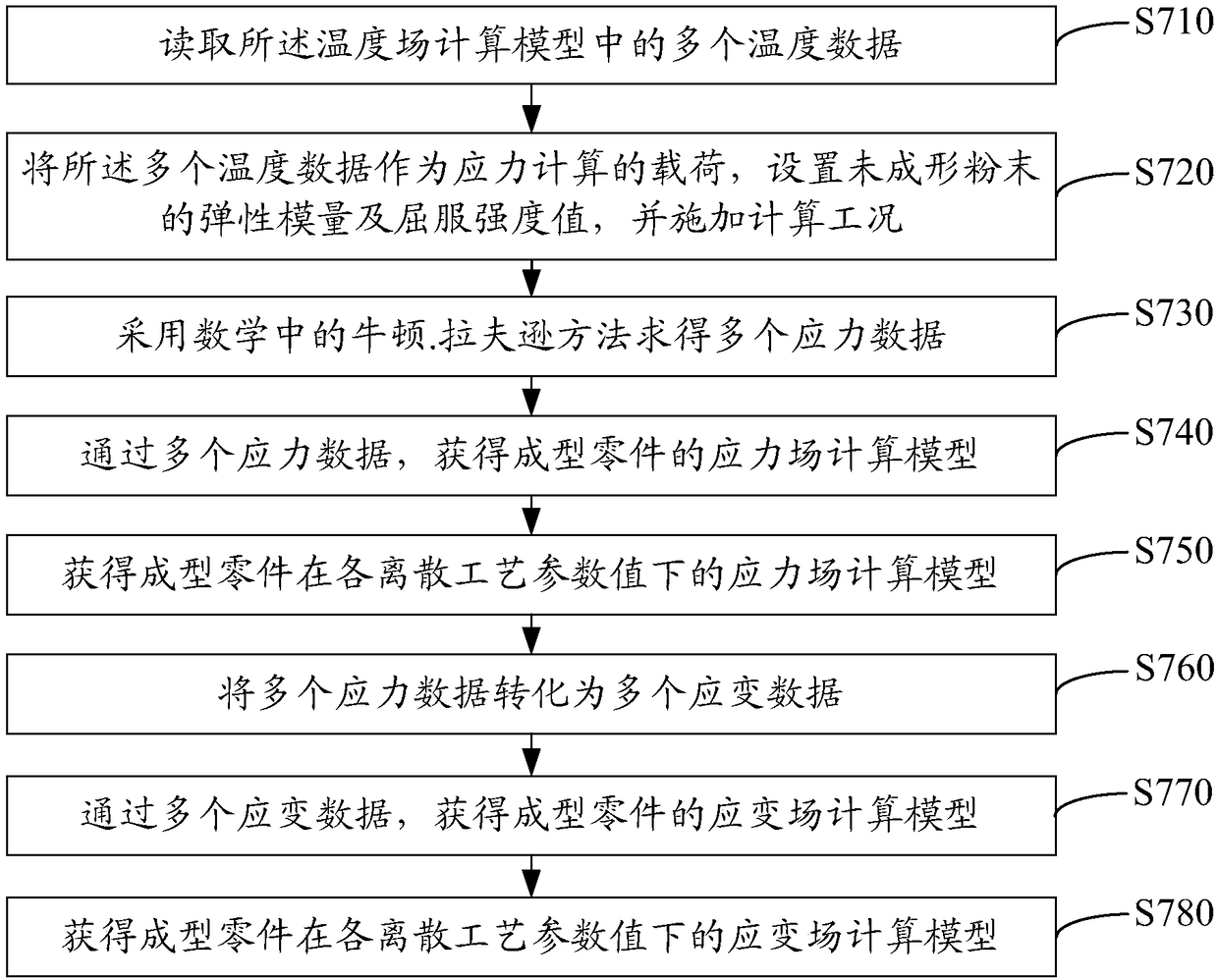
The invention relates to a parameter optimization method for a powder laser 3D (Three-Dimensional) printing forming technology. A computer finite element program is used for carrying out analysis andcalculation on temperature, stress and a strain field when metal powder is formed under different technical parameters, stress and strain values in a part printing process can be tracked, deformationand defects after parts are formed under different technical parameters are predicted, and then, an existing technical parameter is quickly optimized according to an analysis result to quickly obtainthe optimal technical parameter of powder forming. Compared with an existing method for testing through an experiment technology, the method has the advantages of short test period, low test cost andwide powder applicable range and is suitable for printing various types of metal powder.

Description

technical field [0001] The invention relates to the technical field of powder laser additive manufacturing, in particular to a method for parameter optimization of a powder laser 3D printing molding process. Background technique [0002] 3D printing originated from rapid prototyping manufacturing technology. With the rise of metal material 3D printing technology, 3D printing has received widespread attention worldwide. Compared with traditional casting technology, 3D printing technology does not need to prepare molds, which shortens the development cycle. 3D printing technology can not only provide mechanical properties comparable to forging technology, but also realize the molding of complex structural parts, filling the gap in traditional processing technology. [0003] Although 3D printing technology has many technical advantages, choosing the appropriate printing process parameters is the key. Different process parameters have a great impact on the molded parts, such as...

Claims


Application Information

Patent Timeline
IPC IPC(8): G06F17/50
CPCG06F30/23G06F2119/06
Inventor 王燕灵范国成万虹蒋磊肖俊君陈根余陈焱高云峰
Owner HANS LASER TECH IND GRP CO LTD
Learn More