
Large-area super-resolution photoetching device

A super-resolution, large-area technology, applied in photolithography exposure devices, microlithography exposure equipment, optics, etc., can solve the problems of mask substrate limitation and influence, and achieve the effect of easy replacement

Active Publication Date: 2018-05-29
INST OF OPTICS & ELECTRONICS - CHINESE ACAD OF SCI
View PDF4 Cites 5 Cited by
  • Summary
  • Abstract
  • Description
  • Claims
  • Application Information

AI Technical Summary

Problems solved by technology

Off-axis SP excitation illumination has increased the working distance of lithography to the order of hundreds of nanometers, but how to accurately detect and control the gap to ensure the stability and reliability of lithography has become a new technical problem
Capacitive sensors are the most commonly used gap detection detectors. Usually, electrodes are embedded in the mask and the surface of the substrate to form parallel plate capacitance. Although the structure is simple and easy to implement, the mask substrate is limited and will be affected during the exposure process. Drift effect is also obvious

Method used


Image

  • Large-area super-resolution photoetching device
  • Large-area super-resolution photoetching device
  • Large-area super-resolution photoetching device

Examples


Embodiment Construction

[0073] In order to make the objectives, technical solutions, and equipment advantages of the present invention clearer, the present invention will be further described in detail below with reference to the accompanying drawings.

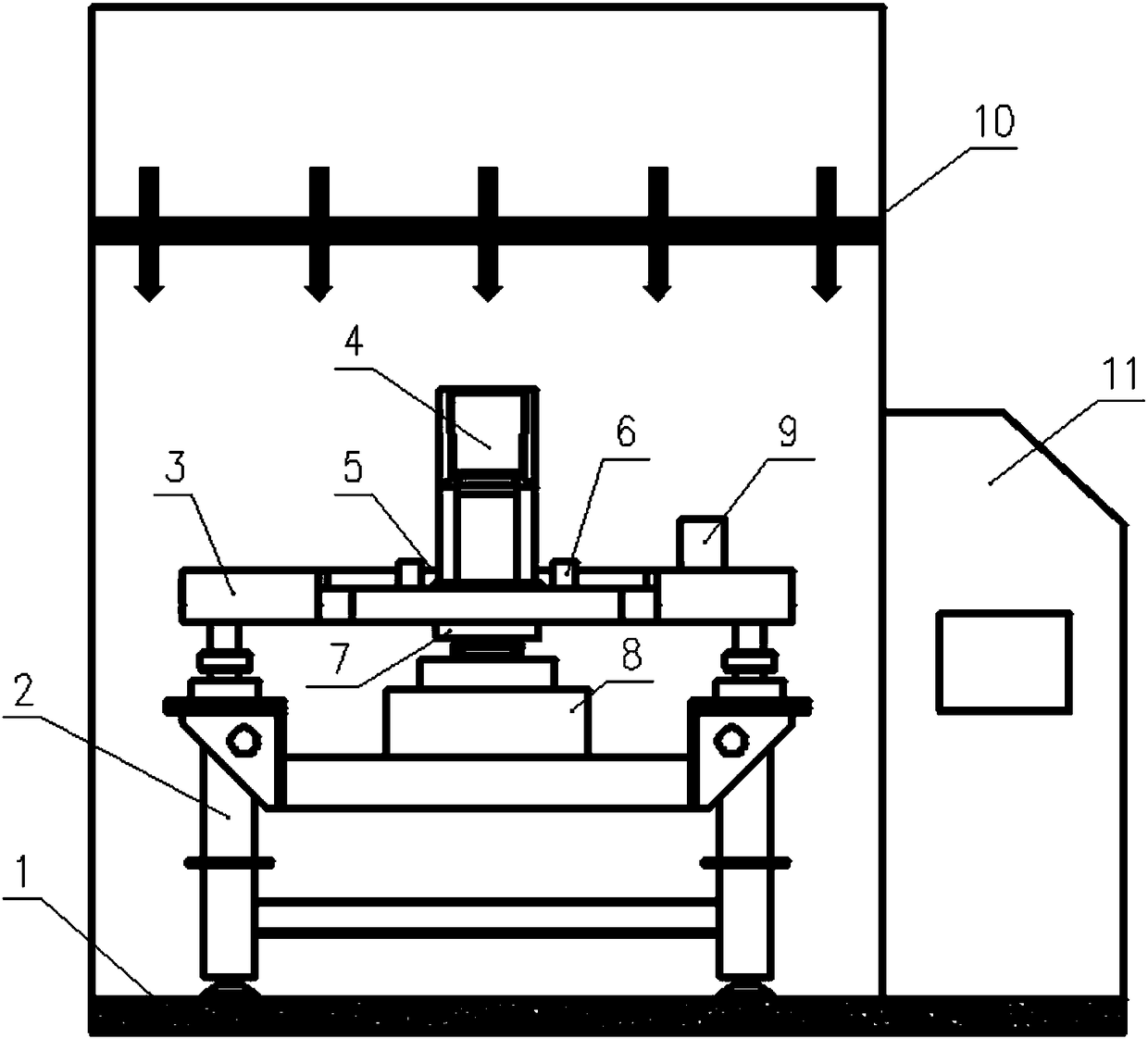
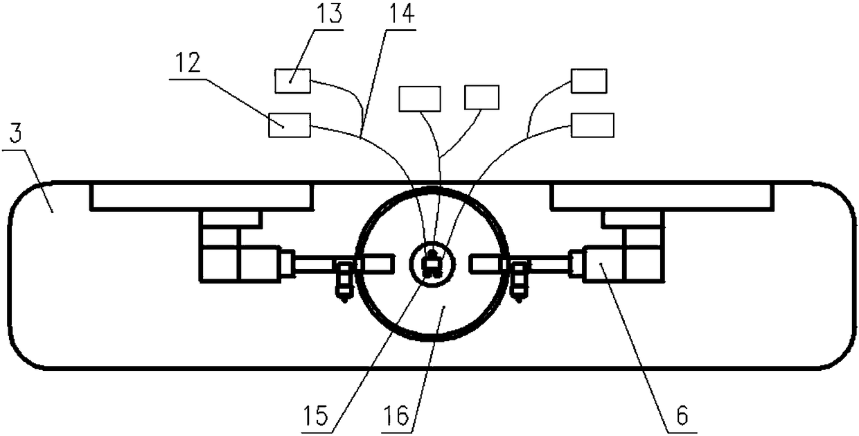
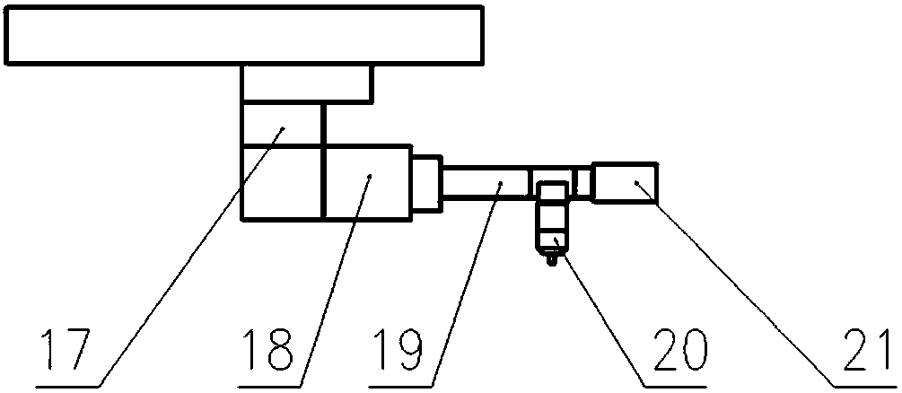
[0074] Reference figure 1 , A large-area super-resolution lithography device, the device is mainly composed of vibration isolation foundation 1, active vibration isolation platform 2, main substrate 3, ultraviolet exposure light source 4, gap detection system 5, alignment module 6, super-resolution lithography lens It is composed of module 7, workpiece table module 8, six-axis laser interferometry system 9, ultra-precision environmental control system 10 and control system 11. Among them, the vibration isolation foundation 1 and the active vibration isolation platform 2 can achieve vibration isolation effects above VC-E; the ultra-precision environmental control system 10 provides the entire super-resolution lithography equipment with a temperature of 22...


PUM


Abstract

The invention discloses a large-area super-resolution photoetching device and belongs to the technical field of super-resolution photoetching equipment. The device comprises a vibration isolation foundation, an active vibration isolation platform, a main base plate, an ultraviolet exposure light source, a gap detection system, an alignment module, a super-resolution photoetching lens module, a workbench module, a laser interferometry system, an ultraprecise environmental control system and a control system. Through an interference technology, the device achieves online gap detection of nanometer level precision; through a precise levelling and gap control technology, the gap photoetching function at tens of nanometer levels is achieved; through a local air control technology of a sheet bearing platform, the large-area super-resolution stepping photoetching function is achieved.

Description

Technical field [0001] The invention belongs to the technical field of lithography equipment, and specifically relates to a large-area super-resolution lithography device. Background technique [0002] The current technologies used for micro-nano structure pattern processing mainly include: proximity lithography, projection lithography, nanoimprint technology and electron beam direct writing technology. [0003] Contact lithography technology is a traditional optical lithography method, in which a pre-made mask is directly exposed to a silicon wafer coated with photoresist. Contact lithography technology has the advantages of high resolution, simple equipment, convenient operation and low cost; but its fatal disadvantage is that the mask and photoresist are in direct contact, which is easy to damage and contaminate the mask, so the service life of the mask Short, multiple use will seriously affect the yield of the chip. Proximity lithography is to avoid defects caused by contact ...

Claims


Application Information

Patent Timeline
Patent Type & Authority Applications(China)
IPC IPC(8): G03F7/20
CPCG03F7/70325G03F7/70358G03F7/70483G03F7/70725
Inventor 罗先刚赵承伟李猛王长涛赵泽宇
Owner INST OF OPTICS & ELECTRONICS - CHINESE ACAD OF SCI
Learn More