
Flushing device and water feeding start control mechanism thereof

A technology of starting control and starting mechanism, applied in the field of bathroom, can solve problems such as inability to realize, and achieve the effects of reliable function, simple operation and simple structure

Pending Publication Date: 2018-05-18
XIAMEN R&T PLUMBING TECH +1
View PDF0 Cites 4 Cited by
  • Summary
  • Abstract
  • Description
  • Claims
  • Application Information

AI Technical Summary

Problems solved by technology

However, in some specific occasions, such as a device for flushing the toilet, the water flow in the early stage of the water inlet valve is used to supply water to the brush ring on the top of the toilet to scrub the wall of the toilet, and stop after a certain period of time. The brush ring of the toilet is supplied with water, and the water inlet valve is switched to feed water to the water tank, which requires the water inlet valve to feed water in advance to supply water to the brush ring of the toilet as soon as possible before the above-mentioned starting water level, that is, the water level in the water tank drops to The water inlet valve needs to start the water inlet before the start water level of the water inlet valve, but in the prior art, when the drain valve discharges water, the water inlet valve needs to wait for the water level in the water tank to drop to the start water level before starting the water inlet. As a result, the water inlet valve needs to wait for the water to enter, and it cannot realize the function that the water inlet valve needs to enter water in advance in certain occasions

Method used


Image

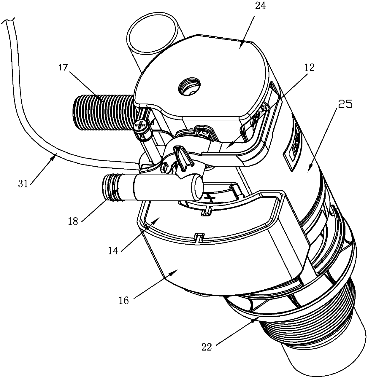
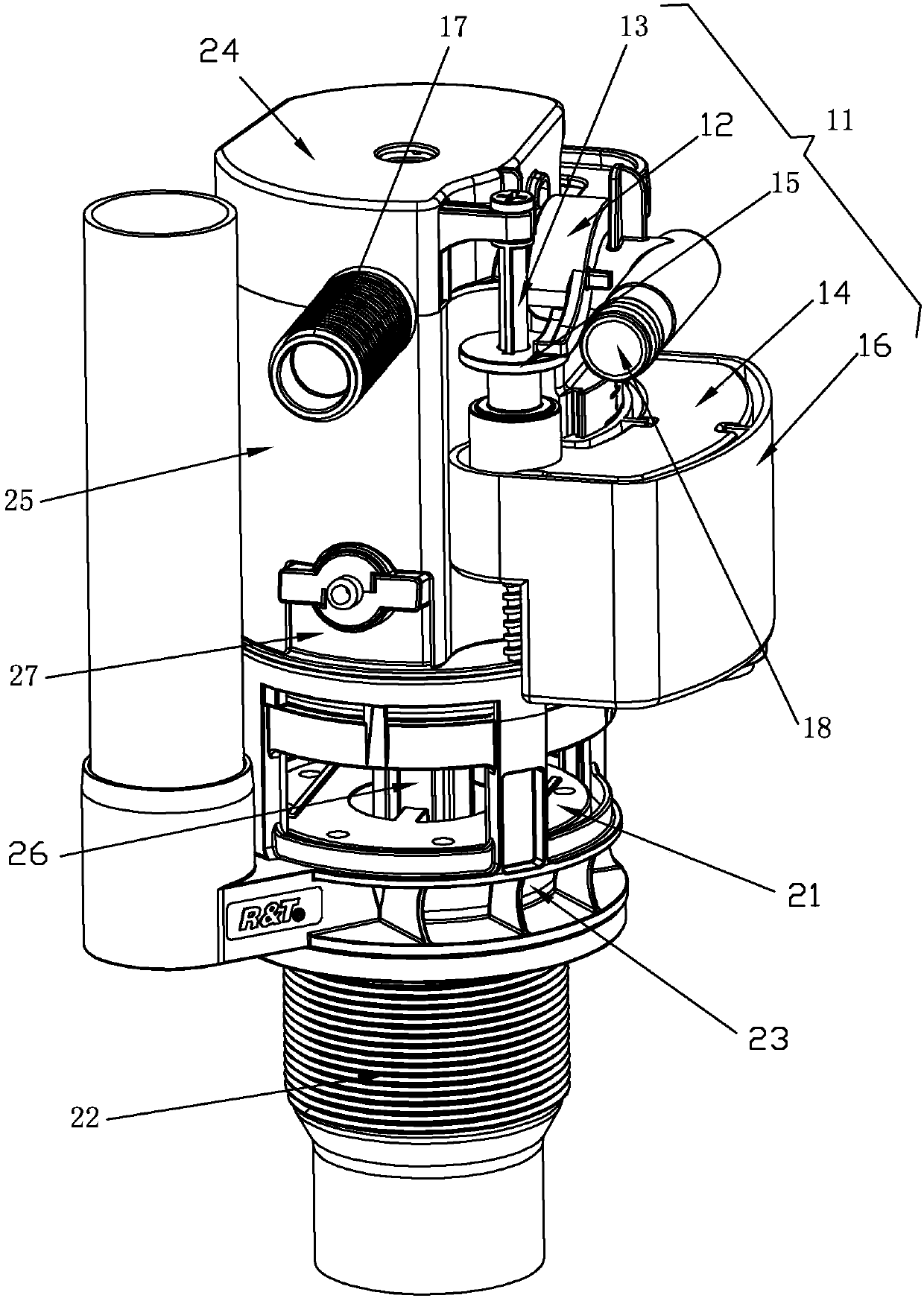
  • Flushing device and water feeding start control mechanism thereof
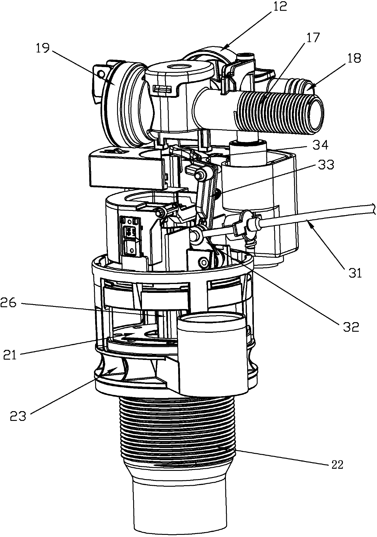
  • Flushing device and water feeding start control mechanism thereof
  • Flushing device and water feeding start control mechanism thereof

Examples


no. 1 example

[0064] (one end of the rotating arm 32 of the start switch is linked with the seal assembly 21, and the other end is linked with the water stop assembly 11)

[0065] like Figures 1 to 15 As shown, in this embodiment, the starting mechanism includes a starting switch, the starting switch is linked with the sealing assembly 21 and opens the water tank drain 23, and the starting switch drives the water-stopping assembly 11 through a connecting rod 33 Move to connect the water inlet channel 17 and the water outlet channel 18 of the water inlet mechanism. Wherein, the start switch includes a wire rope 31 and a rotating arm 32 .

[0066] Rotating arm 32:

[0067] like Figure 14 As shown, the rotating arm 32 is provided with a connection point 321 with a wire rope, a connection point 322 with a connecting rod, and a pivot point 323 with the lifting arm 35; one end of the rotating arm 32 rotates under the traction of the wire rope 31 and The sealing assembly 21 is lifted to open...

no. 2 example

[0074] (One end of the rotating arm 32 of the start switch is linked with the seal assembly 21, and then the seal assembly 21 is linked with the water stop assembly 11)

[0075] like Figures 16 to 18 As shown, the main difference between this embodiment and the first embodiment is that the starting switch is linked with the sealing assembly 21 and opens the water tank drain 23, the starting switch includes a steel wire rope 31 and a rotating arm 32, and the rotating arm 32 One end rotates under the traction of the steel wire rope 31 and lifts the sealing assembly 21. The connecting rod 33 is rotatably mounted on the drainage body 27 above the valve stem 26. When the sealing assembly 21 is lifted, the linkage The connecting rod 33 rotates, and then drives the movement of the water-stop assembly 11. Specifically, the sealing assembly 21 lifts the valve stem 26 and pushes up against one end of the connecting rod 33 to rotate the connecting rod 33. The other end of the connecting...

no. 3 example

[0080] like Figures 19 to 20 As shown, the difference between this embodiment and the above-mentioned second embodiment is that a boss 261 is provided above the valve stem 26. When the sealing assembly 21 is not lifted, the top surface of the boss 261 abuts against one end of the connecting rod 33, sealing When the assembly 21 is lifted, the valve rod 26 of the sealing assembly 21 pushes upward against one end of the connecting rod 33 so that the connecting rod 33 rotates, and then the one end of the connecting rod 33 is separated from the top surface of the boss 261 and abuts against the side of the boss 261, Compared with the above-mentioned second embodiment, the advantage of setting the boss 261 is that it prevents one end of the connecting rod 33 from still abutting against the top of the valve rod 26 after the connecting rod rotates, causing the valve rod 26 to be pushed downward by one end of the connecting rod 33. The reaction force is large, which leads to the proble...


PUM


Abstract

The invention discloses a water feeding start control mechanism. The water feeding start control mechanism includes a water feeding mechanism and a water discharging mechanism; a water-stopping floating barrel of the water feeding mechanism raises with the water level of a water tank so as to allow a water-stopping assembly to cut off a water feeding channel and a water discharging channel of thewater feeding mechanism; the water discharging mechanism includes a sealing assembly capable of opening or closing a water drainage opening of the water tank, and a start mechanism for driving the water-stopping assembly; the water feeding mechanism has a start water level, and the start water level is a water level of the water tank where the water-stopping floating barrel falls with the water level of the water tank so as to allow the water-stopping assembly to communicate with the water feeding channel and the water discharging channel while the start mechanism is not operated; the start mechanism drives the water-stopping assembly to communicate with the water feeding channel and the water discharging channel to achieve water feeding in advance before the water level of the water tankfalls to the starting water level; and then a water feeding function of the water feeding mechanism is achieved before the water level of the water tank falls to the start water level. The water feeding start control mechanism can meet the demand of a specific occasion, is simple in structure, and is reliable in function. The invention also provides a flushing device having the water feeding startcontrol mechanism.

Description

technical field [0001] The invention relates to a flushing device and a water inlet start control mechanism thereof, belonging to the field of sanitary ware. Background technique [0002] At present, the water inlet valve and the drain valve are generally installed in the existing toilet water tank. The water drain valve discharges the water in the water tank. When the starting water level of the valve (starting water level stops and the water tank floats down with the water level of the water tank to the water level of the water tank when the water stop assembly of the water inlet valve just opens the water inlet valve), the water stop float of the falling water inlet valve drives the water inlet of the water inlet valve. The water stop component opens the water inlet valve to feed water into the water tank. However, in some specific occasions, such as a device for flushing the toilet, the water flow in the early stage of the water inlet valve is used to supply water to th...

Claims


Application Information

Patent Timeline
Patent Type & Authority Applications(China)
IPC IPC(8): E03D1/30E03D1/32E03D1/34
CPCE03D1/30E03D1/32E03D1/33E03D1/34E03D1/36E03D2201/30
Inventor 谢岳荣鲁作为鲁展望钟志军王兵
Owner XIAMEN R&T PLUMBING TECH
Learn More