Shrink sleeve damping device, rockfall vibration damping shed tunnel and design method thereof
A technology of vibration-damping devices and design methods, which can be applied to protective equipment, buildings, etc., and can solve problems such as complex maintenance of arc-shaped vibration-damping roofs
- Summary
- Abstract
- Description
- Claims
- Application Information
AI Technical Summary
Problems solved by technology
Method used
Image
Examples
Embodiment 1
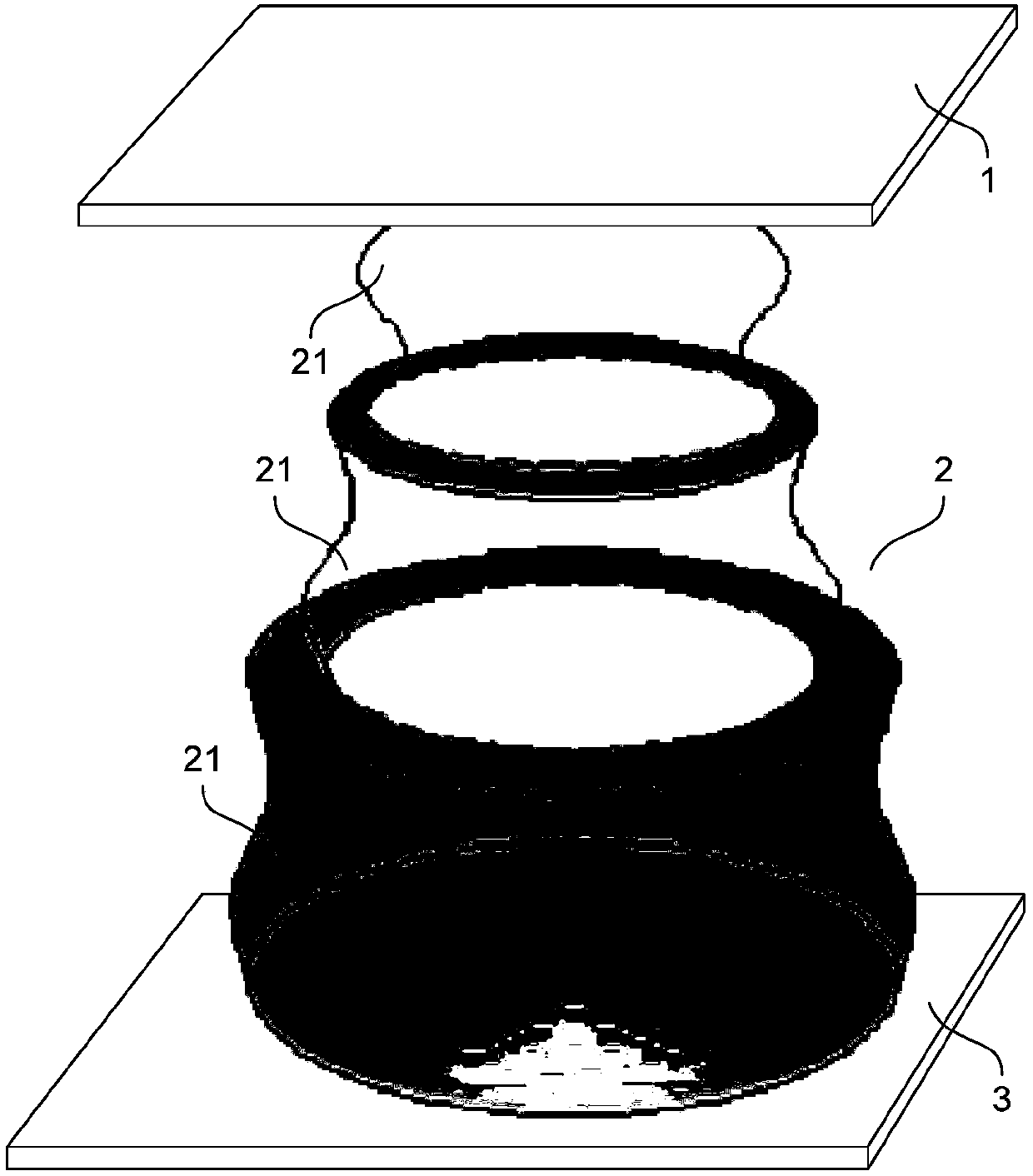
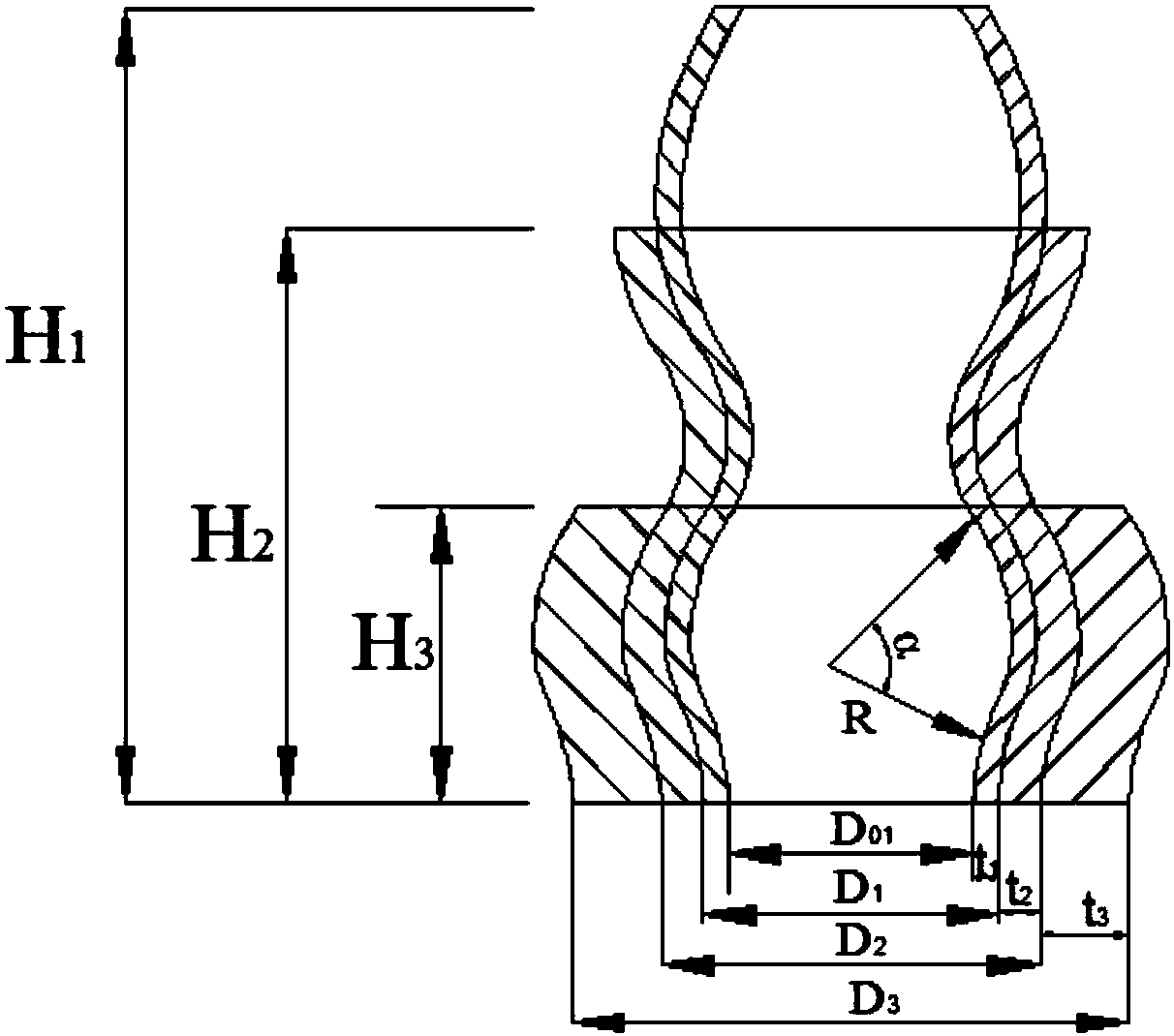
[0073] like Figure 1 ~ Figure 2 As shown, design and process a telescopic sleeve damping device of the present invention.
[0074] According to design requirements, the telescopic sleeve vibration damping device in this embodiment is used for rockfall impact vibration damping in mountainous areas. The impact of the telescopic sleeve vibration damping device mainly comes from the impact of falling rocks, and the general impact energy E 40 , higher impact energy E 80 , the maximum impact energy E max They are all determined according to the method of on-site investigation and investigation of rockfall disasters and survey statistics. The result is E 40 =1000kJ, higher impact energy E 80 =2200kJ, maximum impact energy E max = 4000kJ. Carbon steel is selected as the telescoping sleeve material, and the yield platform stress of the material is determined to be σ=210Mpa by uniaxial compression test. According to the on-site investigation, it is determined that the diameter ...
Embodiment 2
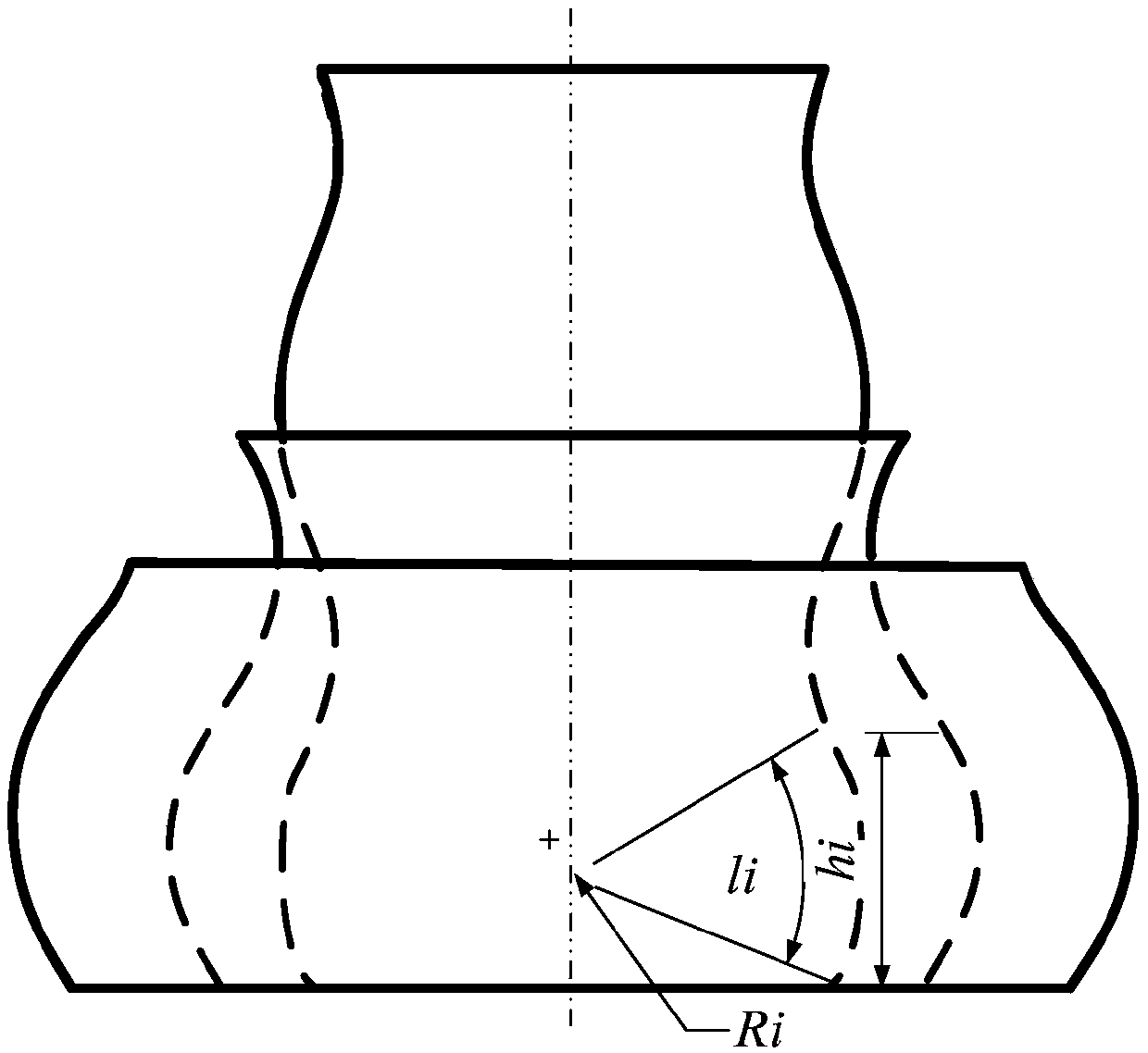
[0081] like image 3 shown. On the basis of Embodiment 1, the arc length l of each layer of the telescopic sleeve vibration damping device is completed 1 , l 2 , l 3 the design of.
[0082] image 3 is a schematic diagram of the vertical section structure of the damping bushing 2 (indicating the arc length l i ). Will D 01 =300mm, D 1 =317mm,t 1 =17mm,D 02 =317mm, D 2 = 360mm, t 2 = 43mm, D 03 =360mm, D 3 = 468 mm, t 3 =108mm are respectively substituted into formula 13 (s takes the value of 0.6, 0.5, 0.4 in turn), and there are each layer of telescopic tubes and the arc length radius R of each segment of telescopic structure 1 =52mm, R 2 =73mm, R 3 = 102mm. Substituting further into Equation 12 there is l 1 =41mm, l 2 =57mm, l 3 =80mm.
[0083] then R 1 =52mm, l 1= 41mm, R 2 =73mm, l 2 =57mm,R 3 =102mm, l 3 =80mm are respectively substituted into formula 14, and the height h of each arc length of each layer of telescopic tube after optimization d...
Embodiment 3
[0085] like Figure 4 , Figure 5 Shown, design and process a rockfall damping shed of the present invention on the basis of Embodiment 1, and its similarity with Embodiment 1 will not be repeated.
[0086] Figure 4 It is a schematic diagram of the side structure of the rockfall damping shed. The rockfall damping shed cave includes a telescopic sleeve vibration damping device; the telescopic sleeve vibration damping device is arranged on the top of the shed cave, the lower bearing plate 3 is connected to the energy dissipator 4, and the lower part of the energy dissipator 4 is connected to the shed cave pillar.
[0087] In this embodiment, the rockfall damping shed is a flat-topped shed.
[0088] Figure 5 It is a schematic diagram of the arrangement structure of the vibration-damping sleeves 2 on the top of the tunnel. The upper force bearing plate 1 and the lower force bearing plate 3 are rectangular, perpendicular to the axis of the shed hole (y coordinate direction) ...
PUM
 Abstract
Description
Claims
Application Information
 - R&D
- Intellectual Property
- Life Sciences
- Materials
- Tech Scout
- Unparalleled Data Quality
- Higher Quality Content
- 60% Fewer Hallucinations
Browse by: Latest US Patents, China's latest patents, Technical Efficacy Thesaurus, Application Domain, Technology Topic, Popular Technical Reports.
© 2025 PatSnap. All rights reserved.Legal|Privacy policy|Modern Slavery Act Transparency Statement|Sitemap|About US| Contact US: help@patsnap.com


