Continuous casting and rolling equipment

A technology of continuous casting and rolling equipment, applied in the direction of metal rolling, etc., can solve the problems of lower production efficiency, lower material quality, less investment, etc., and achieve the effect of improving production efficiency and material quality

Inactive Publication Date: 2018-05-15
蓝婷
View PDF5 Cites 0 Cited by
  • Summary
  • Abstract
  • Description
  • Claims
  • Application Information

AI Technical Summary

Problems solved by technology

[0002] At present, the competition in the steel industry is becoming increasingly fierce, which has promoted the development of the technology for producing finished and semi-finished products in the industry. Compared with the traditional production process, the continuous casting and rolling technology has the advantages of less investment, low production cost, small footprint, and energy saving. Therefore, this technology has been recognized. With the continuous development of this technology, a set of mature continuous casting and rolling technology will be more and more popular; There are certain disadvantages. First, when the solution is in the holding furnace, because the holding furnace contains oxygen, the oxygen will react with the magnesium in the solution to form magnesium oxide, which will form a film on the surface of the solution and deposit in the holding furnace. Secondly, the magnesium When the alloy is in contact with oxygen, an oxide film will be formed, which will reduce the material and make the resulting plate unqualified. Finally, when the plate is off-line, manual transportation will reduce its production efficiency. It can be easily and conveniently processed through the conveyor belt. Sending the plate to the processing site has brought a certain impact in the process of use. For this reason, people have proposed a magnesium alloy continuous casting and rolling equipment

Method used


Image

  • Continuous casting and rolling equipment
  • Continuous casting and rolling equipment
  • Continuous casting and rolling equipment

Examples


Embodiment Construction

[0020] In order to make the technical means, creative features, goals and effects achieved by the present invention easy to understand, the invention will be further elaborated below in conjunction with specific embodiments.

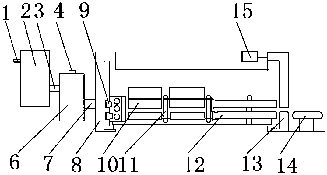
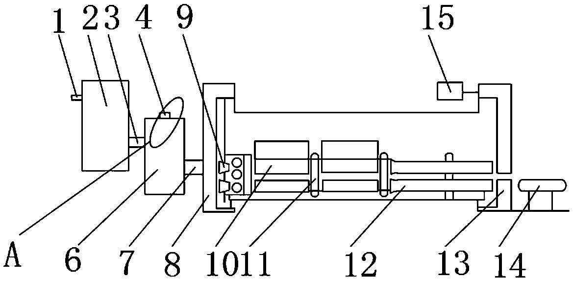
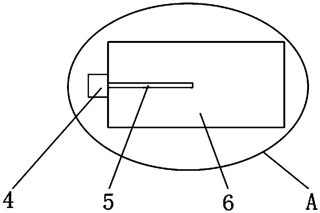
[0021] Such as Figure 1-4 As shown, a continuous casting and rolling equipment includes a smelting furnace 2, a feed pipe 1 is fixedly installed on one side of the smelting furnace 2, and a No. 1 liquid guide tube 3 is fixedly installed on the other side of the smelting furnace 2 , one side outer surface of No. 1 catheter tube 3 is fixedly installed with holding furnace 6, and the upper end outer surface of holding furnace 6 is fixedly installed with pedestal 4, and the lower end outer surface of pedestal 4 is fixedly installed with stirring rod 5, and holding furnace 6 No. 2 catheter tube 7 is fixedly installed on one side outer surface of No. 2 catheter tube 7, No. 1 base 8 is fixedly installed on one side outer surface of No. 2 catheter tube 7, and s...


PUM

PropertyMeasurementUnit
Bending strengthaaaaaaaaaa
Hardnessaaaaaaaaaa

Abstract

The invention discloses continues casting and rolling equipment which comprise a smelting furnace. A feeding pipe is fixedly installed on the outer surface of one side of the smelting furnace. A liquid guide pipe is fixedly installed on the outer surface of the other side of the smelting furnace. A heat insulation furnace is fixedly installed on the outer surface of one side of the first liquid guide pipe. A table base is fixedly installed on the outer surface of the upper end of the heat insulation furnace. A stirring bar is fixedly installed on the outer surface of the lower end of the tablebase. A second liquid guide pipe is fixedly installed on the outer surface of one side of the heat insulation furnace. A first base is fixedly installed on the outer surface of one side of the secondliquid guide pipe. A steel ingot die is fixedly installed on the outer surface of one side of the first base. The continuous casting and rolling equipment is provided with the stirring bar, a nitrogen box and a conveying belt, oxidation films formed on the liquid surface can be reduced, liquid guide pipe blockage is avoided, profile quality can be improved, labor can be reduced, and a better using prospect is brought.

Description

technical field [0001] The invention relates to the field of magnesium alloy continuous casting and rolling, in particular to continuous casting and rolling equipment. Background technique [0002] At present, the competition in the steel industry is becoming increasingly fierce, which has promoted the development of the technology for producing finished and semi-finished products in the industry. Compared with the traditional production process, the continuous casting and rolling technology has the advantages of less investment, low production cost, small footprint, and energy saving. Therefore, this technology has been recognized. With the continuous development of this technology, a set of mature continuous casting and rolling technology will be more and more popular; There are certain disadvantages. First, when the solution is in the holding furnace, because the holding furnace contains oxygen, the oxygen will react with the magnesium in the solution to form magnesium ox...

Claims


Application Information

Patent Timeline
IPC IPC(8): B21B1/46B22D11/114B22D21/04C04B35/577C04B35/80C04B35/622
CPCB21B1/46B22D11/114B22D21/04C04B35/565C04B35/622C04B35/806C04B2235/3244C04B2235/524C04B2235/526C04B2235/5436C04B2235/656
Inventor 蓝婷
Owner 蓝婷
Why Eureka
Try Eureka