
Armature liquid insulating rotary baking and curing apparatus and method

A technology of rotary baking and liquid insulation, which is applied in the direction of electromechanical devices, laying solid insulation, electrical components, etc., and can solve the problems of paint film damage, small amount of paint hanging, and long soaking time

Active Publication Date: 2018-05-11
BEIJING GOLDWIND SCI & CREATION WINDPOWER EQUIP CO LTD
View PDF6 Cites 5 Cited by
  • Summary
  • Abstract
  • Description
  • Claims
  • Application Information

AI Technical Summary

Problems solved by technology

When dipping paint for the first time, in order to make the paint fill into the inside of the winding 200' better, the dipping time should be longer; the second dipping paint is mainly to form a surface paint film, on the other hand, if the second If the time for the first dipping paint is too long, the paint film of the first dipping paint will be damaged instead, and a good dipping paint effect will not be obtained.
There is also a contradiction in the time scale during the two paint dripping processes, which not only affects the amount of paint loss, but also affects the amount of paint on the inner and outer surfaces of the second dipping paint core
The amount of paint hanging is small and there is no need to scrape the paint. However, there must be gaps in the slot insulation, which may cause water ingress and moisture inhalation to damage the insulation (the so-called "breathing phenomenon" of porous insulating materials in the slot)
[0036] All in all, when the traditional winding 200' and the ferromagnetic component 100' are insulated, there is a contradiction. If the varnish can penetrate well, the loss of the varnish cannot be prevented; if the loss of the varnish is reduced, it is difficult for the varnish to penetrate well.

Method used


Image

  • Armature liquid insulating rotary baking and curing apparatus and method
  • Armature liquid insulating rotary baking and curing apparatus and method
  • Armature liquid insulating rotary baking and curing apparatus and method

Examples


Embodiment Construction

[0171] In order to enable those skilled in the art to better understand the technical solutions of the present invention, the present invention will be further described in detail below with reference to the accompanying drawings and specific embodiments.

[0172] Please refer to Figure 14 , Figure 14 It is a schematic structural diagram of a specific embodiment of the armature baking device provided by the present invention.

[0173] The armature of the motor includes ferromagnetic parts (or magnetically conductive parts) and windings 200 (ie coils), such as Figure 14 As shown, the ferromagnetic component 100, also called the iron core, can be formed by stacking a number of ferromagnetic laminations 100a along the axial direction. The ferromagnetic laminations 100a can be, for example, silicon steel sheets or ferrite sheets. The structure and the winding manner of the winding 200 can be understood with reference to the background technology, which is not limited in this embodime...


PUM


Abstract

The invention discloses an armature liquid insulating rotary baking and curing apparatus and a rotary baking method. A ferromagnetic part of an armature is provided with a plurality of winding slots into which windings can be embedded, the winding slots are arranged along a circumferential direction of the ferromagnetic part, the rotary baking apparatus also comprises an air seal part, and the airseal part can be used for injecting air towards slot openings of the winding slots. Under pressure caused by air injection, impregnation liquid can be prevented from flowing out from the winding slots under the effects of gravity; radial loss of the impregnation liquid along slit openings between the winding slots can be reduced in paint trickling processes and rotary baking and curing processesfollowing vacuum pressure impregnation of the armature; filling and impregnating saturation rates of the impregnation liquid can be improved after impregnation operation, cavities can be prevented from being formed in internal slit openings, slit openings via which the impregnation liquid naturally flows out can be blocked first during the processes, and capability of preventing intrusion of moisture and other mediums in external environment can be improved.

Description

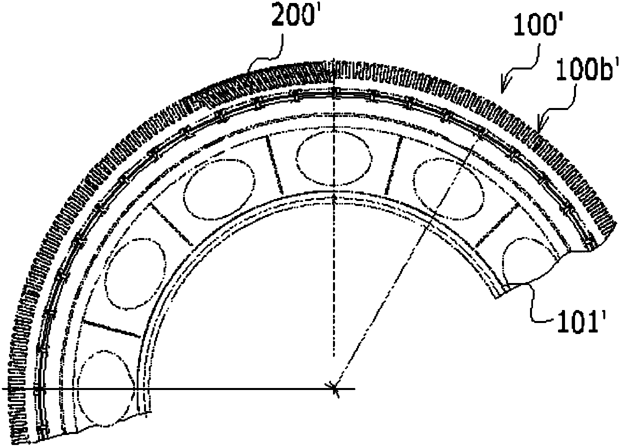
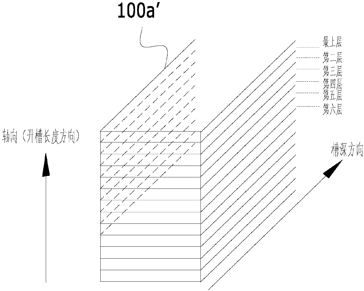
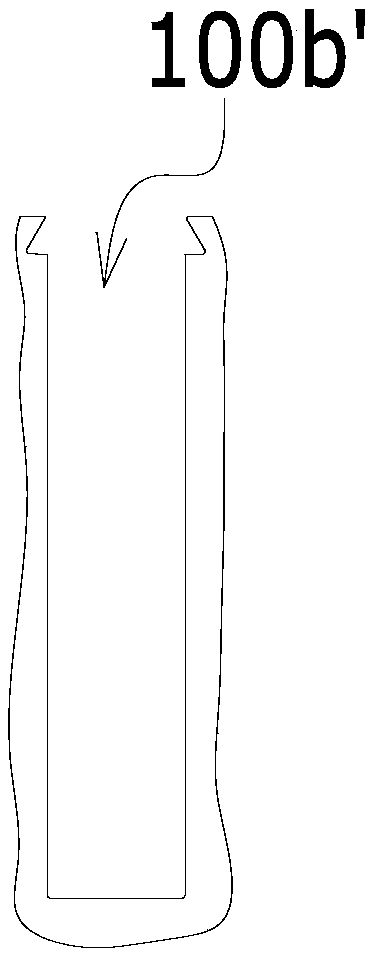
Technical field [0001] The invention relates to the technical field of motor manufacturing, in particular to an armature liquid-insulated rotary baking curing device and a rotary baking method, so as to prevent loss and promote solidification during the rotary baking process. Background technique [0002] Please refer to figure 1 , 2 , figure 1 It is a schematic diagram of the winding and its ferromagnetic components in the wind turbine structure, showing a part of the entire ferromagnetic component circumference, which is fan-shaped; figure 2 Schematic diagram of ferromagnetic components. [0003] The ferromagnetic part 100' of the armature is formed by stacking iron core laminations 100a'. The iron core laminations 100a' are, for example, silicon steel sheets or ferrite sheets, such as figure 2 As shown, the stacking direction is the axial direction of the final ferromagnetic part 100'. [0004] Such as image 3 As shown, image 3 It is a schematic diagram of a single core lamina...

Claims


Application Information

Patent Timeline
IPC IPC(8): H02K15/12H02K15/10
Inventor 马盛骏
Owner BEIJING GOLDWIND SCI & CREATION WINDPOWER EQUIP CO LTD
Learn More