A 3D Deformation Measurement Method Based on Synthetic Wavelength Dual Light Source Shearing Speckle Interference

A technology of three-dimensional deformation and synthesis of wavelengths, which is applied in the field of optical imaging, can solve the problems of low precision and poor anti-interference, and achieve the effects of high precision, large measurement range and fast speed

Inactive Publication Date: 2019-09-24
QIQIHAR UNIVERSITY
View PDF9 Cites 0 Cited by
  • Summary
  • Abstract
  • Description
  • Claims
  • Application Information

AI Technical Summary

Problems solved by technology

[0006] The purpose of the present invention is to solve the problems of low precision and poor anti-interference in three-dimensional deformation measurement, and provide a three-dimensional deformation measurement method based on synthetic wavelength dual light source shearing speckle interference

Method used


Image

  • A 3D Deformation Measurement Method Based on Synthetic Wavelength Dual Light Source Shearing Speckle Interference
  • A 3D Deformation Measurement Method Based on Synthetic Wavelength Dual Light Source Shearing Speckle Interference
  • A 3D Deformation Measurement Method Based on Synthetic Wavelength Dual Light Source Shearing Speckle Interference

Examples


specific Embodiment approach 1

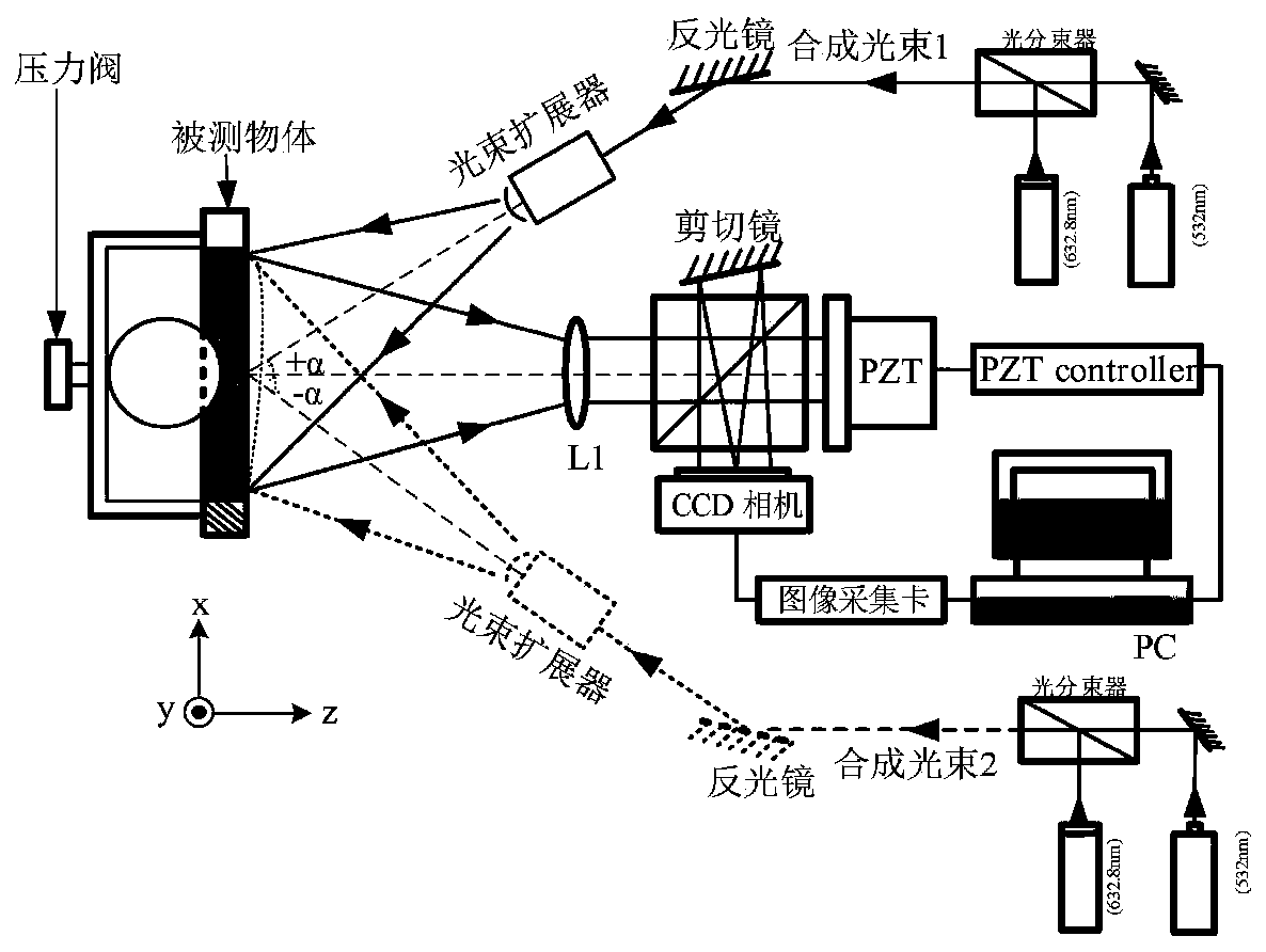
[0046] Specific implementation mode one: as figure 1 As shown, what is described in this embodiment is a three-dimensional deformation measurement method based on synthetic wavelength dual-light source shearing speckle interference, and the steps of the method are as follows:

[0047] Step 1: Two beams of red laser and green laser with different wavelengths pass through the optical beam splitter, and are irradiated by the reflector and beam expander and placed on the measured object in the vacuum box, reflected on the surface of the measured object, and the reflected light passes through The convex lens L1 performs light interference through the shearing mirror in the shearing interference device, and collects the interference image in the CCD camera;

[0048] Step 2: Control the PZT phase shift through the PZT controller (piezoelectric ceramic controller). The red laser passes through the R channel of the color camera, and the green laser passes through the G channel of the c...

Embodiment 1

[0085] Assume that in the selected measurement system, the diode-pumped laser emits green light with a wavelength of λ g =532nm, the helium-neon laser emits red light with a wavelength of λ r =632.8nm, due to the good coherence of the laser, after the two laser beams are coherent, the energy of the center spot of the beam is enhanced, and a high-power coherent beam can be obtained, which makes the wavelength longer and the measurement range larger, which helps to reduce the degree of spectrum aliasing , whose synthetic equivalent wavelength is λ s :

[0086]

[0087] After calculation, the synthetic wavelength can be obtained, that is, λ s = 3.3398 μm.


PUM


Abstract

The invention relates to a three-dimensional deformation measurement method based on shearing speckle interference of double light sources with synthetic wavelengths, belonging to the technical field of optical imaging. The method is as follows: the red and green lasers respectively pass through the optical beam splitter, irradiate the object to be measured through the reflector and the beam expander, and reflect on its surface. The interference image is collected in the CCD camera; the PZT phase shift is controlled by the piezoelectric ceramic controller, the red laser passes through the R channel of the color camera, and the green laser passes through the G channel of the color camera, which are respectively recorded by the CCD camera at the same time; the pressure in the vacuum box is adjusted by the pressure valve. Pressure, the pressure value is displayed by the pressure gauge; the interference image is Fourier transformed, and the relationship between the number of synthetic wavelength phase fringes and the number of single wavelength fringes is calculated; the in-plane displacement derivative array and the out-of-plane displacement derivative array are calculated, according to the optical measurement system Geometric characteristics, and then obtain the three-dimensional deformation matrix of the object, and realize the three-dimensional deformation measurement of the object.

Description

technical field [0001] The invention belongs to the technical field of optical imaging, and in particular relates to a three-dimensional deformation measurement method based on shearing speckle interference of double light sources with synthetic wavelengths. Background technique [0002] As the main measurement methods, digital speckle interferometry and hybrid photometry have achieved certain research results in 3D deformation measurement, but there are still some problems in the following aspects: [0003] (1) The measurement optical path is complex and inconvenient to operate, the measurement range is small, and the requirements for the environment and hardware equipment are high, which cannot meet the engineering environment measurement. [0004] (2) When measuring the depth deformation caused by defects, the speckle interference fringe pattern collected on the CCD is too dense, and undersampling occurs. Commonly used digital image processing methods fail, and the real p...

Claims


Application Information

Patent Timeline
Patent Type & Authority Patents(China)
IPC IPC(8): G01B11/16
Inventor 魏连锁郭媛胡现成
Owner QIQIHAR UNIVERSITY
Why Eureka
Try Eureka