Power transmission device and power transmission method

A technology of power transmission device and output shaft, which is applied in the direction of transmission device, transmission device parts, gear transmission device, etc., can solve the problems of extremely high processing technology requirements, poor structural impact resistance, limited application range, etc., and achieve safe and reliable operation , stable control speed, safe and reliable transmission process

Active Publication Date: 2018-05-08
BEVELOID ROBOT JOINT TECHSHANGHAI CO LTD
View PDF5 Cites 2 Cited by
  • Summary
  • Abstract
  • Description
  • Claims
  • Application Information

AI Technical Summary

Problems solved by technology

Existing reducers mainly include cycloidal gear boxes, ordinary planetary gearboxes, worm gear boxes and harmonic gearboxes, among which the reduction ratio range of ordinary single-stage and double-stage planetary gearboxes is small, and worm gear boxes The deceleration ratio is relatively large, but the input speed is low, and the application range is limited. The most critical cycloidal pinwheel gearbox currently used is crankshaft drive, and the transmission accuracy is high, but the mechanism is complex and the processing technology is extremely high; the harmonic gearbox is surface. Contact multi-tooth meshing, compact structure, but the output adopts elastic piece type cup ring, the meshing position and the output part must undergo elastic deformation, and the structure has poor impact resistance

Method used


Image

  • Power transmission device and power transmission method
  • Power transmission device and power transmission method
  • Power transmission device and power transmission method

Examples


Embodiment 1

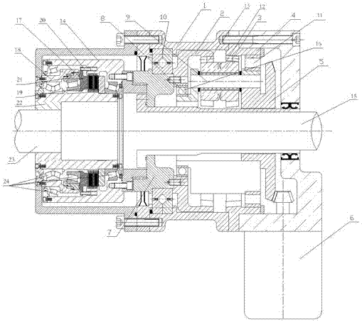
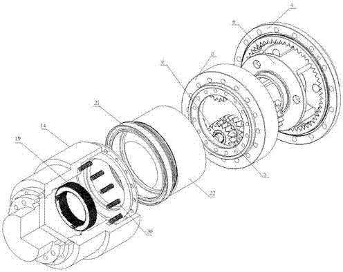
[0040] The use method and principle of the power transmission device 30 of the present invention are as follows: the drive mechanism 6 drives the transmission structure 5, the planet carrier 8, the planetary pin 9 between the transmission structure 5 and the planetary carrier 8, and the planetary pin 9 is provided with The double-thickened planetary gear 3 rotates coaxially. Since the double-thickened planetary gear 3 meshes with the fixed second thickened ring gear 4 through the second gear structure 12 provided on the surface, the double-thickened planetary gear 3 The thick planetary gear 3 rotates around the planetary pin 9. Since the double-thickened planetary gear 3 also meshes with the first thickened ring gear 2 through the first gear structure 13 provided on the surface, the first thickened tooth The ring 2 rotates, and the output shaft housing 14 outside the output shaft 23 of the thickened planetary gearbox is driven to rotate through the first thickened ring gear 2 i...

Embodiment 2

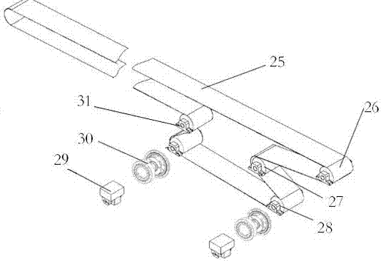
[0042] see image 3 , is a schematic diagram of applying the power transmission device 30 of the present invention to a bulk material conveyor. The conveyor belt 25 is wound and arranged on several driving rollers. The output shaft 23 of the power transmission device 30 is connected, and the input end of the power transmission device 30 is connected with the drive motor 29. The several drive rollers are arranged symmetrically on the left and right sides of the conveyor belt 25. Taking the right side as an example, when conveying The right side of the belt 25 is provided with a first driving roller 26, the left side of the first driving roller 26 is provided with a second driving roller 27, and the right side of the second driving roller 27 is provided with a third driving roller 28. The first driving roller 26 , the second driving roller 27 and the third driving roller 28 are arranged in a V shape.

[0043] The technical scheme of the present invention realizes the effect of ...


PUM


Abstract

The invention relates to the technical fields of power transmission equipment and method, in particular to a power transmission device and a power transmission method. The power transmission device comprises a thickened planetary gear box and a torque control device, wherein a transmission structure is arranged at the input end of the thickened planetary gear box; the transmission structure is connected with a planetary carrier through a plurality of planetary pins; double thickened planetary gears are further sleeved to the planetary pins; a first gear structure and a second gear structure are respectively arranged on the surfaces of the double thickened planetary gears; a first thickened gear ring is connected with an output shaft casing on the outer side of the output shaft of the thickened planetary gear box. Compared with the prior art, the power transmission device has the advantages that the design is reasonable, the structure is compact, a driving motor can be started in a no-load manner, load is stably and slowly started, the starting time is prolonged, and the accelerated moment of load is reduced, so that the service performance of a conveying belt can be improved, the service life of the conveying belt can be prolonged, meanwhile automatic control of adjustable and flexible speed regulation in a driving system is convenient to realize, and the device is easy to mount and dismount.

Description

technical field [0001] The present invention relates to the technical field of power transmission equipment and methods, in particular to a power transmission device and a power transmission method. Background technique [0002] At present, large-capacity, long-distance, and high-speed bulk material conveyors are widely used in the transportation of bulk materials such as coal and ore. There are two main ways to start the transmission device: one is the electrode, the moment-limiting hydraulic coupling Due to the influence of the torque-limited hydraulic coupling during the drive transmission process, the start-up time is short, and the belt start cannot be accurately controlled according to the control curve requirements. There are problems such as poor start-up stability and large impact, which will lead to The serious consequences of transverse cracks in the conveyor belt have become the biggest hidden danger of production safety; the other is composed of frequency conver...

Claims


Application Information

Patent Timeline
IPC IPC(8): F16H3/44F16H57/023F16H57/08B65G23/04
CPCB65G23/04F16H3/44F16H57/023F16H57/08F16H2057/02034F16H2057/02069F16H2057/087
Inventor 戴飞孙键
Owner BEVELOID ROBOT JOINT TECHSHANGHAI CO LTD
Why Eureka
Try Eureka