Power conveying device and power conveying method

A technology of power transmission device and output shaft, applied in the direction of transmission device, transmission device parts, gear transmission device, etc., can solve the problems of extremely high processing technology requirements, poor structural impact resistance, limited application scope, etc., and achieve reliable technology, The effect of small clearance and extended start-up time

Pending Publication Date: 2018-09-21
BEVELOID ROBOT JOINT TECHSHANGHAI CO LTD
View PDF9 Cites 0 Cited by
  • Summary
  • Abstract
  • Description
  • Claims
  • Application Information

AI Technical Summary

Problems solved by technology

Existing reducers mainly include cycloidal gear boxes, ordinary planetary gearboxes, worm gear boxes and harmonic gearboxes, among which the reduction ratio range of ordinary single-stage and double-stage planetary gearboxes is small, and worm gear boxes The deceleration ratio is large, but the input speed is low, and the application range is limited. The most critical application at present is that the cycloidal pinwheel gearbox is driven by a crankshaft, and the transmission accuracy is high, but the mechanism is complicated and the processing technology is extremely high; the harmonic gearbox is Surface contact and multi-tooth meshing, compact structure, but the output is an elastic piece cup-shaped ring, the meshing position and the output part must be elastically deformed, and the structure has poor impact resistance

Method used


Image

  • Power conveying device and power conveying method
  • Power conveying device and power conveying method
  • Power conveying device and power conveying method

Examples


Embodiment 1

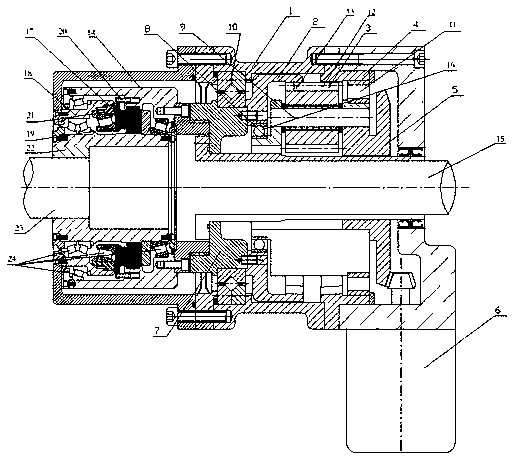
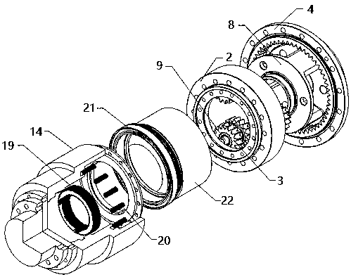
[0043] The use method and principle of the power transmission device 30 of the present invention are as follows: the drive mechanism 6 drives the transmission structure 5, the planet carrier 8, the planetary pin 9 between the transmission structure 5 and the planetary carrier 8, and the planetary pin 9 is provided with The single-thickness planetary gear 3 rotates coaxially. Since the single-thickness planetary gear 3 meshes with the fixed second thickening ring gear 4 through the gear structure provided on the surface, the single-thickness planetary gear 3 rotates around the planetary pin 9, because the single-thickened planetary gear 3 also meshes with the first thickened ring gear 2 through the gear structure provided on the surface, so that the first thickened ring gear 2 rotates, and in turn The first thickened ring gear 2 drives the output shaft housing 14 on the outside of the thickened planetary gearbox output shaft 23 to rotate, and the output shaft housing 14 drives t...

Embodiment 2

[0045] see image 3 , is a schematic diagram of applying the power transmission device 30 of the present invention to a bulk material conveyor. The conveyor belt 25 is wound and arranged on several driving rollers. The output shaft 23 of the power transmission device 30 is connected, and the input end of the power transmission device 30 is connected with the drive motor 29. The several drive rollers are arranged symmetrically on the left and right sides of the conveyor belt 25. Taking the right side as an example, when conveying The right side of the belt 25 is provided with a first driving roller 26, the left side of the first driving roller 26 is provided with a second driving roller 27, and the right side of the second driving roller 27 is provided with a third driving roller 28. The first driving roller 26 , the second driving roller 27 and the third driving roller 28 are arranged in a W shape.

[0046] The technical solution of the present invention realizes the effects ...


PUM


Abstract

The invention relates to the technical field of power conveying equipment and methods, in particular to a power conveying device and a power conveying method. The power conveying device comprises a variable-thickness planetary gear box and a torque control device. A transmission structure is arranged at the input end of the variable-thickness planetary gear box and connected with a planetary framethrough a plurality of planetary pins. Each planetary pin is sleeved with a double variable-thickness planetary gear, wherein the surface of the double variable-thickness planetary gear is provided with a first gear structure and a second gear structure. A first variable-thickness gear ring is connected with an output shaft shell on the outer side of an output shaft of the variable-thickness planetary gear box. Compared with the prior art, the power conveying device is reasonable in design and compact in structure, a driving motor can be started in a no-load mode and is stably and slowly started when loaded, the starting time is prolonged, the loading acceleration moment is lowered, and therefore the use performance of a conveying belt is improved, and the service life of the conveying belt is prolonged. Meanwhile, automatic control over controllable and flexible speed adjustment of a driving system is better facilitated, and mounting and dismounting are easy.

Description

technical field [0001] The present invention relates to the technical field of power transmission equipment and methods, in particular to a power transmission device and a power transmission method. Background technique [0002] At present, large-capacity, long-distance, and high-speed bulk material conveyors are widely used in the transportation of bulk materials such as coal and ore. There are mainly two ways to start the transmission device: one is the electrode, and the moment-limiting hydraulic Composed of a coupler and a reducer, because it is affected by the torque-limited hydraulic coupler during the drive transmission process, the start-up time is short, and the belt start cannot be precisely controlled according to the control curve requirements, and there are problems such as poor start-up stability and large impact , its serious consequences will cause transverse cracks in the conveyor belt, which becomes the biggest hidden danger of production safety; the other ...

Claims


Application Information

Patent Timeline
IPC IPC(8): B65G23/24F16H3/44F16H57/023F16H57/08B65G23/04
CPCF16H3/44F16H57/023F16H57/08B65G23/04B65G23/24F16H2057/02034F16H2057/02069F16H2057/087
Inventor 戴飞孙键
Owner BEVELOID ROBOT JOINT TECHSHANGHAI CO LTD
Why Eureka
Try Eureka