Torque transmission control device and using method thereof
A control device and torque transmission technology, applied in the transmission device, transportation and packaging, conveyor and other directions with synchronous propulsion components, which can solve the problems of short start-up time, transverse cracks in the conveyor belt, poor start-up stability, etc., and achieve easy installation and The effect of dismantling, prolonging the starting time, reducing the acceleration torque
- Summary
- Abstract
- Description
- Claims
- Application Information
AI Technical Summary
Problems solved by technology
Method used
Image
Examples
Embodiment 1
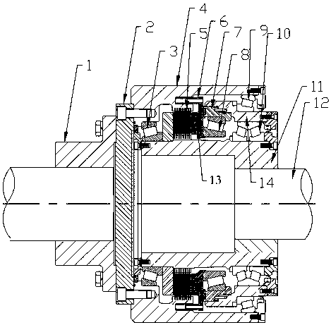
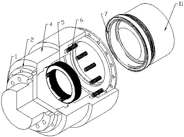
[0024] The use method and principle of the power transmission device of the present invention are as follows: the torque transmission control device is directly installed on the rear side of the torque output device, that is, the output shaft of the torque output device and the connecting plate of the torque transmission control device are connected through the input coupling Fixedly connected, the connecting plate is connected with the housing of the torque transmission control device through bolt connection or pin connection or other connection methods, so that the output shaft of the torque output device can drive the rotation of the housing, thereby driving the The output shaft rotates. At this time, the control piston structure exerts pressure on the clutch group provided between the housing and the output shaft, so that the gap between the clutch group and the housing and the gap between the clutch group and the output shaft The gaps between several static friction plates...
Embodiment 2
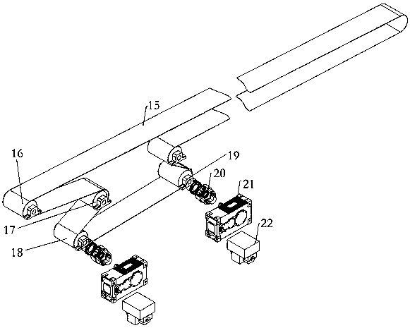
[0026] see image 3 , is a schematic diagram of applying the torque transmission control device of the present invention to a bulk material conveyor. The conveyor belt is wound and arranged on several driving rollers. The output shaft of the device is connected, the torque transmission control device is connected to the rear side of the existing gearbox, and the several drive rollers are symmetrically arranged on the left and right sides of the conveyor belt, so as to image 3 Take the left side as an example, there is a first driving roller on the left side of the conveyor belt, a second driving roller on the lower right side of the first driving roller, and a third driving roller on the lower left side of the second driving roller. The first driving drum, the second driving drum and the third driving drum are arranged in a W shape.
PUM
 Abstract
Description
Claims
Application Information
 - R&D Engineer
- R&D Manager
- IP Professional
- Industry Leading Data Capabilities
- Powerful AI technology
- Patent DNA Extraction
Browse by: Latest US Patents, China's latest patents, Technical Efficacy Thesaurus, Application Domain, Technology Topic, Popular Technical Reports.
© 2024 PatSnap. All rights reserved.Legal|Privacy policy|Modern Slavery Act Transparency Statement|Sitemap|About US| Contact US: help@patsnap.com


