Automatic continuous type film coating technology for pole groups

A pole group and coating technology, applied in the field of pole group automatic continuous coating process, can solve the problems of poor coating quality, complicated process, low coating efficiency, etc., and achieve the effect of good effect, improved efficiency and simple structure.

Active Publication Date: 2018-05-04
阜阳市广联普惠自动化技术有限公司
View PDF6 Cites 2 Cited by
  • Summary
  • Abstract
  • Description
  • Claims
  • Application Information

AI Technical Summary

Problems solved by technology

[0008] One of the purposes of the present invention is to provide an extremely automatic continuous coating process for the deficiencies of the prior art, by setting the feeding process, unwinding process, film unfolding process, cutting process, coating process and The output process and the orderly combination of each process overcome the problems of low coating efficiency, poor coating quality and cumbersome process in the extreme group coating process

Method used


Image

  • Automatic continuous type film coating technology for pole groups
  • Automatic continuous type film coating technology for pole groups
  • Automatic continuous type film coating technology for pole groups

Examples


Embodiment 1

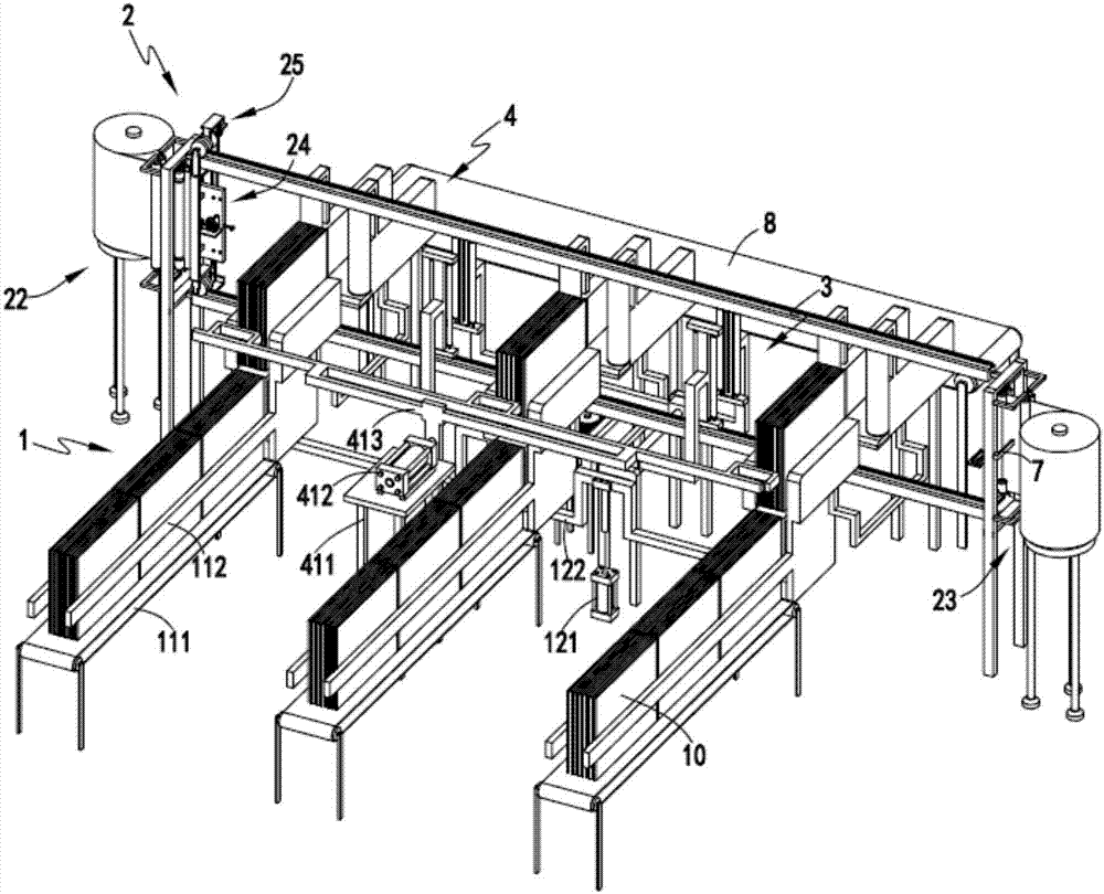
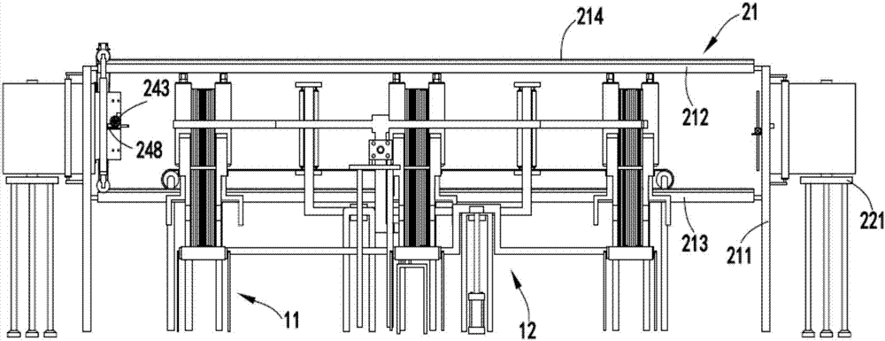
[0072] like figure 1 , figure 2 , image 3 , Figure 4 , Figure 5 , Image 6 , Figure 7 , Figure 8 , Figure 9 and Figure 10 As shown in the figure, an automatic continuous coating process of the pole group includes the following production steps:

[0073] Step 1, the feeding process, the conveyor belt transports the pole group to be coated to the feeding station, and the lifting mechanism 12 lifts the pole group at the feeding station to the coating station;

[0074] Step 2, unwinding process, unwinding the reel film on the first unwinding station, and a limiting mechanism located at the first unwinding station to limit the end of the unwinding film;

[0075] Step 3, the film unwinding process, the adsorption mechanism 24 adsorbs and fixes the end of the film at the first unwinding station described in the step 2, and after the adsorption and fixation is completed, it is driven by the traction mechanism 25 along the guide mechanism 21. The movement unwinds the ...

Embodiment 2

[0089] like figure 1 , figure 2 , image 3 , Figure 4 , Figure 5 , Image 6 , Figure 7 , Figure 8 , Figure 9 and Figure 10 As shown, an automatic continuous coating system for pole groups includes a feeding device 1, and the feeding device 1 includes a horizontal conveying mechanism 11 for horizontally and continuously conveying the pole groups 10 and a lifting mechanism for lifting the pole groups 10. Agency 12;

[0090] Film unwinding device 2, described film unwinding device 2 comprises guiding mechanism 21, the first unwinding mechanism 22 and the second unwinding mechanism 23 that are respectively arranged on guiding mechanism 21 two ends, are used for first unwinding mechanism 22 and The end of the roll film on the second unwinding mechanism 23 is adsorbed and fixed by adsorption mechanism 24 and the traction mechanism 25 for driving the adsorption mechanism 24 and the end of the film to move along the guide mechanism 21;

[0091] Cutting device 3, descr...

Embodiment 3

[0115] like figure 1 , figure 2 , image 3 , Figure 4 , Figure 5 , Image 6 , Figure 7 , Figure 8 , Figure 9 and Figure 10 As shown, the parts that are the same as or corresponding to those in the second embodiment are marked with the corresponding reference numerals in the second embodiment. For the sake of simplicity, only the differences from the second embodiment will be described below. The difference between the third embodiment and the second embodiment is that further, the cutting mechanism 31 includes a sliding seat 311, a cutting assembly a312 and a cutting assembly b313 which are slidably arranged on the sliding seat 311 and symmetrically arranged front and rear;

[0116] The cutting assembly a312 includes a slider a3121 that cooperates with the guide rod b3111 on the sliding seat 311 to slide, a connecting frame a3122 that is fixedly connected with the sliding block a3121, a mounting frame a3123 that is arranged at the end of the connecting frame a3122...


PUM


Abstract

The invention relates to an automatic continuous type film coating technology for pole groups. The technology comprises processes as follows: a feeding process: the pole groups are conveyed to a feeding station and are lifted to a coating station by a lifting mechanism; an unwinding process: a roll film on a first unwinding station is unwound, and the film is limited by a limiting mechanism; a film unfolding process: the film in the station is adsorbed and fixed by an adsorption mechanism, the film is unfolded along a guiding mechanism under driving of a drawing mechanism, and when the film moves to a second unwinding station, the film is released and the operation is switched to fix the film in the second unwinding station; a cutting process: after the film is unfolded, the tail part of the film is cut off by a transverse cutting assembly, the film is subjected to equivalent cutting by a cutting mechanism and the end part of the film is limited; a coating process: after equivalent cutting, the pole groups are pushed by a pushing mechanism to move towards the film and coated with the film by a coating mechanism; an output process: the coated pole groups are output by an output station. According to the automatic continuous type film coating technology for the pole groups, the problems of low coating efficiency, poor coating quality and tedious technology in a pole group film coating process are solved.

Description

technical field [0001] The invention relates to the technical field of lead-acid battery electrode group coating equipment, in particular to an automatic continuous coating process for electrode groups. Background technique [0002] The operation mode of the traditional battery stacking machine is easy to cause quality problems such as diaphragms or pole plates in series, uneven height, and the pole group is polluted by the dust accumulated on the platform, which not only affects the work efficiency, but also affects the battery. The occurrence of two important quality unqualified items, such as virtual welding and short circuit of the internal pole plate, will wrap a layer of film on the pole group. In the battery industry, the coating operation of the pole group is generally used on a simple platform and completely relies on manual labor. For encapsulation, the necessary tools are lacking. [0003] Authorized announcement number CN201520895976.X is a Chinese utility model...

Claims


Application Information

Patent Timeline
IPC IPC(8): B65B11/02B65B61/06B65B41/14H01M10/12
CPCB65B11/02B65B41/14B65B61/06H01M10/12Y02E60/10Y02P70/50
Inventor 郭长杰
Owner 阜阳市广联普惠自动化技术有限公司
Why Eureka
Try Eureka