Digital rock physical model construction method and device

A petrophysical model and construction method technology, applied in the field of digital petrophysical model construction, can solve problems such as insufficient consideration, high cost, and difficulty in satisfying actual production, and achieve the effect of improving authenticity and effectiveness

Inactive Publication Date: 2018-04-27
CHINA UNIV OF PETROLEUM (BEIJING)
View PDF3 Cites 3 Cited by
  • Summary
  • Abstract
  • Description
  • Claims
  • Application Information

AI Technical Summary

Problems solved by technology

[0004] However, in the current digital petrophysical imaging method, the physical imaging technology needs to destroy the rock formation to obtain imaging samples. The acquisition process is very time-consuming and costly, and it is difficult to meet the needs of actual production.
In the numerical reconstruction method, the random reconstruction is based on a specific information of the core to construct its 3D model through an algorithm. Therefore, the 3D model only shows the shape of the relevant information, which has certain limitations and cannot accurately and completely characterize the formation rocks. However, the influence of gravity and inter-particle friction on the particle deposition morphology during the particle deposition process is not fully considered. Compared with the random reconstruction method, the process method takes the gravity and internal friction of mineral particles into account in the numerical reconstruction process. Natural settlement process under the action of , buoyancy, etc., and after the initial settlement process is completed, it can simulate the compaction and cementation process of the formation, and the characterization of connectivity and seepage characteristics is more accurate
However, The process method proposed by et al. has low algorithmic efficiency in the search and calculation of the stable state position of the particles, and its motion direction does not consider the direction of motion caused by the new resultant force after the collision between the depositing mineral particles and the deposited mineral particles change
The discrete element modeling method adopted by Jin et al. considers the sedimentation of mineral particles under the action of gravity, internal friction, and buoyancy, which is closer to the real situation, but the algorithm is more complicated when calculating the overall potential energy of sedimentary minerals, and the amount of calculation is large.
Calculation efficiency is low. For the common multi-mineral and multi-scale pore formation types, it is impossible to effectively establish a multi-scale multi-mineral stratigraphic model, so it cannot provide accurate guidance for actual exploration and mining.

Method used


Image

  • Digital rock physical model construction method and device
  • Digital rock physical model construction method and device
  • Digital rock physical model construction method and device

Examples


Embodiment 2

[0097] Figure 10 is a schematic structural diagram of the digital rock physics model construction device provided by Embodiment 2 of the present invention, as Figure 10 As shown, on the basis of the first embodiment above, the present invention also provides a digital petrophysical model construction device 4, including:

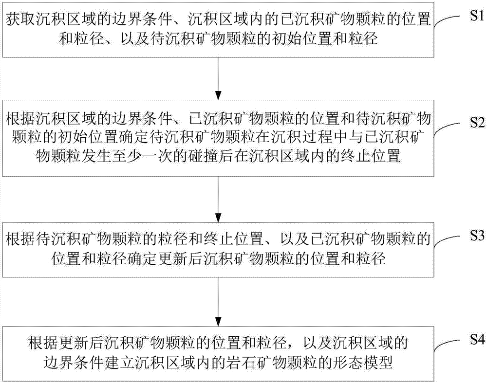
[0098] The acquisition module 41 is configured to acquire the boundary conditions of the deposition area, the position and particle size of the deposited mineral particles in the deposition area, and the initial position and particle size of the mineral particles to be deposited.

[0099] It should be noted that when the acquisition module 41 of this embodiment acquires the above information, the boundary conditions of the deposition area, the position and particle size of the deposited mineral particles in the deposition area, and the initial position and particle size of the mineral particles to be deposited All can be set according to actual needs, whi...

Embodiment 3

[0107] also, Figure 11 It is a schematic structural diagram of the digital rock physics model construction device provided by Embodiment 3 of the present invention. Such as Figure 11 As shown, on the basis of the first and second embodiments above, the third embodiment of the present invention provides a digital petrophysical model construction device 5, which includes:

[0108] The memory 51 is used to store instructions; specifically, the storage objects of the memory 52 include software and modules. The processor 52 is configured to execute the instructions stored in the memory 51 to execute the digital petrophysical model construction method provided in the first embodiment above. The processor 52 executes various functions of the digital petrophysical model building device 5 and processes data by running or executing software programs and / or modules stored in the memory 51 and calling data stored in the memory 51 .

[0109] Specifically, the processor 52 is configure...


PUM


Abstract

The invention provides a digital rock physical model construction method and device. The method comprises steps that boundary conditions of a deposition area, the position and the particle size of deposited mineral particles in the deposition area and the initial position and the particle size of to-be-deposited mineral particles are acquired; according to the boundary conditions of the depositionarea, the position of the deposited mineral particles and the initial position of the to-be-deposited mineral particles, the termination position of the to-be-deposited mineral particles in the deposition area after at least one collision between the to-be-deposited mineral particles and the deposited mineral particles is determined; according to the particle size and the termination position ofthe to-be-deposited mineral particles and the position and the particle size of the deposited mineral particles, the position and the particle size of the updated deposited mineral particles are determined; a morphological model of the rock mineral particles in the deposition area is established based on the position and the particle size of the deposited mineral particles after update and the boundary conditions of the deposition area. The method is advantaged in that authenticity and validity of the digital rock physical model can be effectively improved, and instructive advices can be provided for petroleum exploration.

Description

technical field [0001] The invention relates to the technical field of petroleum exploration and development, in particular to a digital petrophysical model construction method and device. Background technique [0002] The deposition process of formation rocks has a great influence on the exploration and exploitation of petroleum, which will affect various physical properties of rocks, including the particle size distribution of minerals, the porosity, connectivity and pore shape of rocks, etc. The stratum modeling method can effectively simulate the three-dimensional stratum model after the actual stratum deposition, and provide guidance for oil exploration and production. Stratigraphic modeling methods can be divided into reservoir-scale models, formation or logging-scale models, core-scale models, and pore-scale models according to scale. [0003] The current methods for stratigraphic modeling mainly include digital petrophysical imaging methods and numerical reconstruct...

Claims


Application Information

Patent Timeline
Patent Type & Authority Applications(China)
IPC IPC(8): G01V99/00
CPCG01V99/005
Inventor 肖立志田志廖广志
Owner CHINA UNIV OF PETROLEUM (BEIJING)
Why Eureka
Try Eureka