
Power flow transfer identification algorithm based on multi-branch removal and deviation paths

A technology of power flow transfer and identification algorithm, which is applied in the direction of AC network, calculation, circuit device with different sources of the same frequency, etc., can solve the problems of increasing the chain trip of transmission lines, complicated verification calculation, lack of power grid, etc., so as to avoid modification. , improve the efficiency of the algorithm, reduce the effect of the amount of matrix operations

Inactive Publication Date: 2018-04-24
NORTH CHINA ELECTRIC POWER UNIV (BAODING)
View PDF0 Cites 8 Cited by
  • Summary
  • Abstract
  • Description
  • Claims
  • Application Information

AI Technical Summary

Problems solved by technology

In this context, at present, the power grid dispatching center arranges the power grid operation mode in strict accordance with the requirements of the "Guidelines for the Safety and Stability of Power Systems", and strictly implements the "N-1" rule during operation, such as equipment maintenance, unit control, etc. When changing, eliminate safety hazards in time, so that the probability of chain tripping of branch circuits caused by a single component breaking is getting smaller and smaller; however, most domestic power grids have not yet reached the strength that can resist severe faults of multiple branch circuits on the same section. This is mainly because on the one hand, the calibration calculation is complicated, and on the other hand, to meet the safety calibration of multi-branch removal, it is necessary to increase the thermal stability limit power of the line.
Since the power grid lacks countermeasures for the disconnection of multiple branches, once such a fault occurs, the backup protection will cut off the line, which greatly increases the probability of chain tripping of the transmission line

Method used


Image

  • Power flow transfer identification algorithm based on multi-branch removal and deviation paths
  • Power flow transfer identification algorithm based on multi-branch removal and deviation paths
  • Power flow transfer identification algorithm based on multi-branch removal and deviation paths

Examples


Embodiment Construction

[0025] The technical solution of the present invention will be described in further detail below with reference to the accompanying drawings and embodiments.

[0026] A power flow transfer recognition algorithm based on multi-branch cutting and deviation paths described in the present invention includes the following steps:

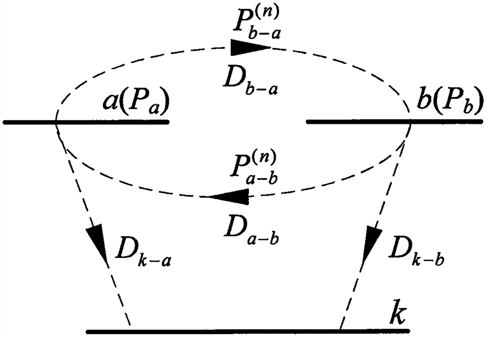
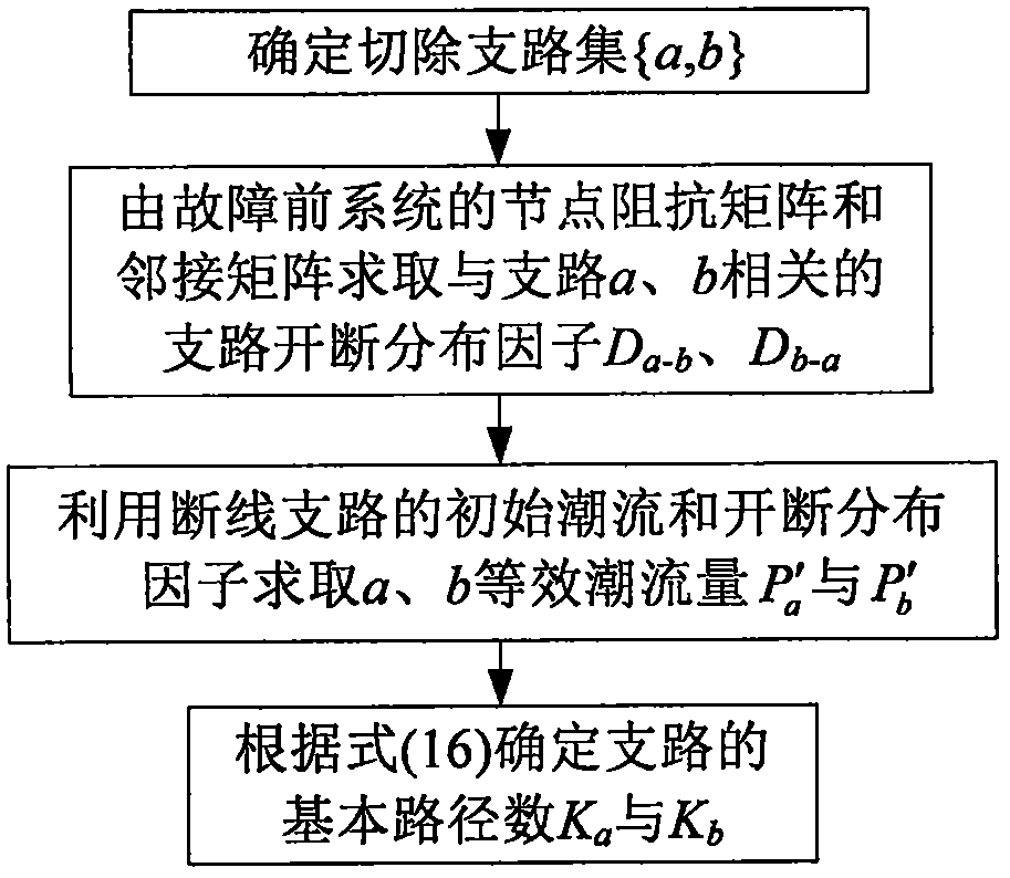
[0027] Step 1: Analyze the composition of the power flow transferred to the non-faulty branch. When multi-branch cutting occurs, the transferred power flow on branch k can be regarded as multiple branches with equivalent power flow as the initial power flow and then transferred to The superposition of the power flow on branch k simplifies the cutting of multiple branches into the case of cutting off multiple single branches, avoiding a large number of correction calculations for the node impedance matrix in the DC method, and realizing the rapid estimation of the power flow transfer;

[0028] Assume that the initial power flows are P a with P b Branches...


PUM


Abstract

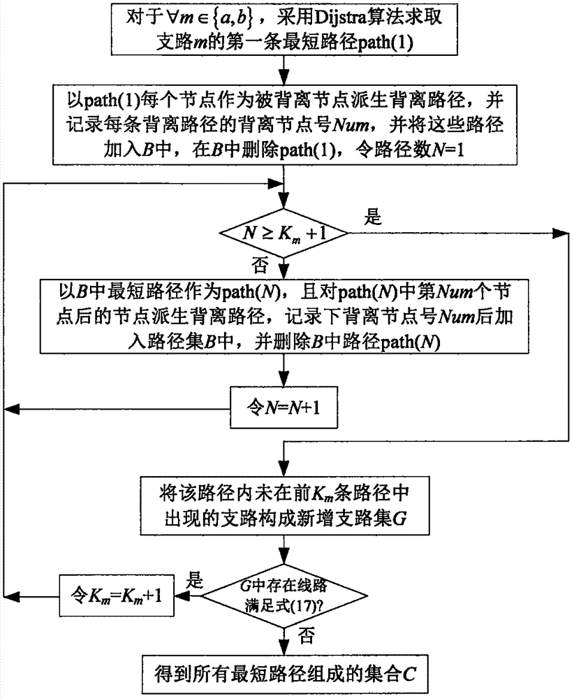
The invention provides a power flow transfer identification algorithm based on multi-branch removal and deviation paths, which includes the following steps: I, analyzing the composition of a power flow transferred to a non-fault branch, wherein, under the condition of multi-branch removal, the transferred power flow on a branch k can be seen as the superposition of power flow transferred to the branch k after multiple branches with an equivalent power flow as an initial power flow are separately broken; II, based on a deviation path algorithm in graph search, searching for the first K shortestpaths between the two end nodes of removed branches, and determining the regional scope with large power flow transfer; and III, giving a transmission section selection principle by considering the real-time running state of the power grid, identifying a branch set with large increase in actual power flow, and finding out lines of which the power flow increases reversely. Important improvement ismade in power flow transfer estimation, K value selection and section criterion for removed branches.

Description

technical field [0001] The invention relates to the field of power system protection and safety control of a grid company, in particular to a power flow transfer identification algorithm based on multi-branch cutting and deviation paths. Background technique [0002] The power flow shift caused by faulty branch cutting in the power grid is an important reason for chain cutting accidents of transmission lines in various countries in the world in recent years, which seriously endangers the safe and stable operation of the system. In this context, the current power grid dispatching center arranges the power grid operation mode in strict accordance with the requirements of the "Guidelines for the Safety and Stability of Power Systems", and strictly implements the "N-1" rule during operation, such as equipment maintenance, unit control and other operations. When changing, eliminate safety hazards in time, so that the probability of chain tripping of branch circuits caused by a si...

Claims


Application Information

Patent Timeline
IPC IPC(8): H02J3/00H02J3/06G06Q10/04G06Q50/06
CPCG06Q10/047G06Q50/06H02J3/0073H02J3/06
Inventor 任建文易琛何培成
Owner NORTH CHINA ELECTRIC POWER UNIV (BAODING)
Learn More