
Fuel cell-combined power supply system and energy management method

A fuel cell and power supply system technology, applied in the direction of DC power supply parallel operation, circuit devices, DC network circuit devices, etc., can solve the problems of complex derivation and calculation process, high requirements for real-time computing and processing capabilities of hardware equipment, unfavorable smooth and stable control, etc.

Inactive Publication Date: 2018-04-20
SHANGHAI DIANJI UNIV
View PDF4 Cites 9 Cited by
  • Summary
  • Abstract
  • Description
  • Claims
  • Application Information

AI Technical Summary

Problems solved by technology

Although the state machine control method is simple, its management strategy depends on the past empirical rules of the system. The jitter between the two state edges is not conducive to smooth and stable control; the fuzzy logic energy management technology based on empirical rules uses the membership function and If- Then rule, but the rule designer is required to be very familiar with the components of the combined power supply system, and needs previous expert experience to assist in the design; other energy methods based on model predictive control, neural networks, etc., although through exquisite design and tedious mathematical calculations It can achieve better fuel utilization or efficiency, but the entire derivation and calculation process is very complicated, and the requirements for real-time calculation and processing capabilities of hardware equipment are relatively high, which is not conducive to the promotion of practical engineering applications

Method used


Image

  • Fuel cell-combined power supply system and energy management method
  • Fuel cell-combined power supply system and energy management method
  • Fuel cell-combined power supply system and energy management method

Examples


Embodiment Construction

[0029] In order to make the technical means, creative features, goals and effects achieved by the present invention easy to understand, the present invention will be further elaborated below in conjunction with illustrations and specific embodiments.

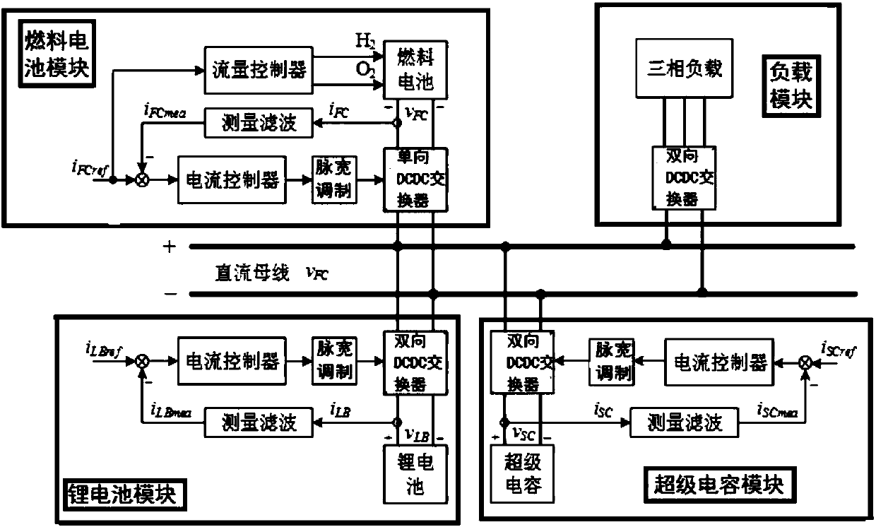
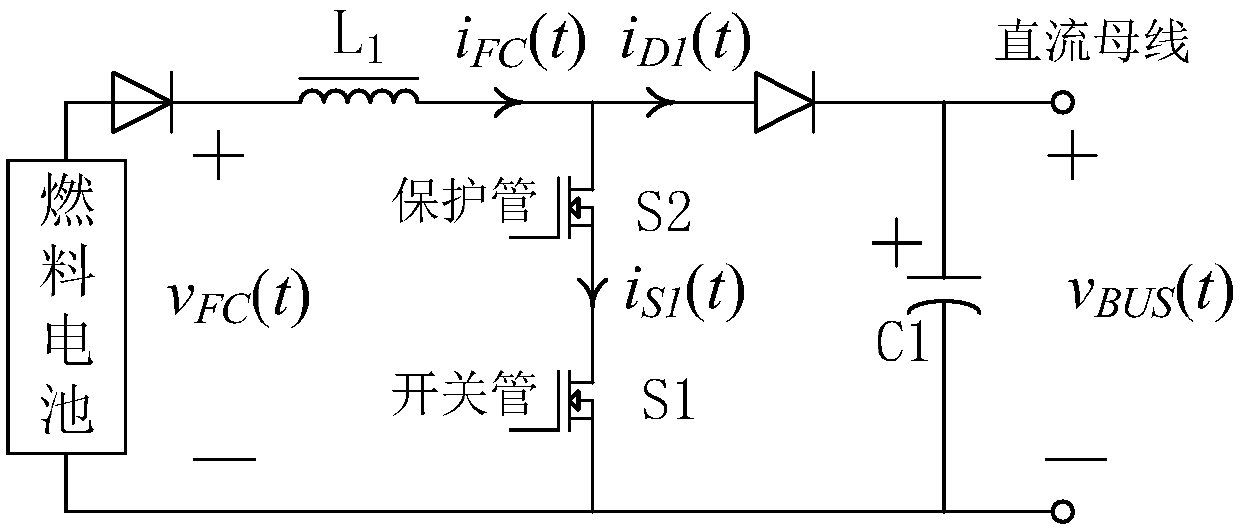
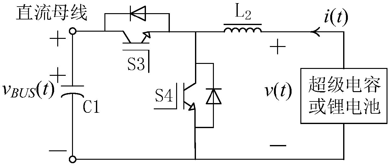
[0030] Such as Figure 1 to Figure 12As shown, a fuel cell combined power supply system proposed by the present invention includes a fuel cell module, a lithium battery module, a supercapacitor module, a DC bus, a load module, a DC bus voltage control loop, a supercapacitor voltage control loop, and a lithium battery voltage control loop. , lithium battery charging control loop, simulation software, energy management system; fuel cell module includes: fuel cell, unidirectional DCDC converter, flow controller, measurement filter, pulse width modulator, current controller, negative feedback input terminal, One end of the unidirectional DCDC converter is connected to the positive and negative poles of the DC bus, and the other end ...


PUM


Abstract

The invention discloses a fuel cell-combined power supply system, which comprises a fuel cell module, a lithium battery module, a supercapacitor module, a DC bus, a load module, a DC bus voltage control loop, a supercapacitor voltage control loop, a lithium battery voltage control loop, a lithium battery charging control loop, simulation software and an energy management system, wherein the fuel cell module comprises a fuel cell, a unidirectional DC-DC converter, a flow controller, a measurement filter, a pulse width modulator, a current controller and a negative feedback input end; one end ofthe unidirectional DC-DC converter is connected with positive and negative electrodes of the DC bus and the other end is connected with the fuel cell; the measurement filter is arranged between the fuel cell and the positive electrode of the unidirectional DC-DC converter; the measurement filter is output to the current controller; the current controller is output to the pulse width modulator; the pulse width modulator is connected with the unidirectional DC-DC converter; the flow controller is used for controlling the content of hydroxide ions of the fuel cell; and an input end of the flow controller is connected with the negative feedback input end.

Description

technical field [0001] The invention relates to the technical field of proton exchange membrane fuel cell design, in particular to a fuel cell combined power supply system and an energy management method. Background technique [0002] A fuel cell is a clean and efficient distributed power source that converts the chemical energy of hydrogen-containing fuel directly into electrical energy without a combustion process under the action of a catalyst. Proton exchange membrane fuel cell (PEMFC for short), as the most likely commercialized fuel cell, has the advantages of low operating temperature, high current density, and fast response, and has broad application prospects; however, PEMFC is a complex The electrochemical system, which adjusts the flow and pressure of the reaction gas in real time according to the load power requirements, has a relatively slow time response constant, and the electrochemical reaction is easily disturbed by external parameters such as humidity, temp...

Claims


Application Information

Patent Timeline
IPC IPC(8): H02J1/10
CPCH02J1/10H02J2300/30
Inventor 胡鹏石瑛刘军蒋赢商雨青马豫超
Owner SHANGHAI DIANJI UNIV
Learn More