
Micro-droplet control method based on laser direct writing technology

A laser direct writing, micro droplet technology, applied in nanotechnology, laser welding equipment, devices for coating liquid on surfaces, etc., can solve the problems of low resolution and poor flexibility, and achieve high resolution and low production cost. , The method is simple and controllable

Active Publication Date: 2018-04-20
SHENZHEN TECH UNIV
View PDF4 Cites 16 Cited by
  • Summary
  • Abstract
  • Description
  • Claims
  • Application Information

AI Technical Summary

Problems solved by technology

[0006] In view of the above-mentioned deficiencies in the prior art, the object of the present invention is to provide a micro-droplet manipulation method based on laser direct writing technology, aiming to solve the problems of low resolution and poor flexibility of the existing micro-droplet manipulation method

Method used


Image

  • Micro-droplet control method based on laser direct writing technology
  • Micro-droplet control method based on laser direct writing technology
  • Micro-droplet control method based on laser direct writing technology

Examples


Embodiment 1

[0042] Anisotropic patterns are designed by laser direct writing technology to drive micro-droplets in a directional way:

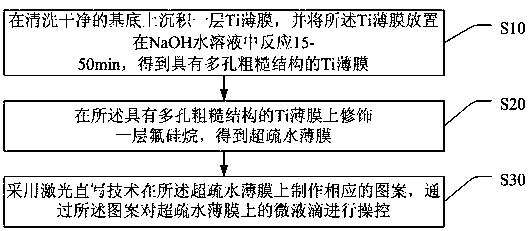
[0043] 1. Deposit a 100 nm-thick Ti film on a cleaned substrate by magnetron sputtering, and then react the Ti film in a 10 M sodium hydroxide solution at 60 °C for 30 minutes to obtain a Ti film with a porous rough structure. Film; A layer of fluorosilane was modified by chemical vapor deposition on the surface of a Ti film with a porous rough structure at 120°C for 4 hours to obtain a super-hydrophobic film;

[0044] 2. Use laser direct writing technology to directly write anisotropic patterns point by point on the super-hydrophobic film. During the laser sintering process, the roughness of the super-hydrophobic surface is reduced, thereby changing the wettability of the processed part;

[0045]3. Spraying water mist on the patterned film, since the micro-droplets are affected by the surface energy gradient and the Laplace pressure on the anisotropic pa...

Embodiment 2

[0048] Directional driving of micro-droplets by processing wettability patterns of different shapes on superhydrophobic substrates by laser direct writing technology

[0049] 1. Deposit a 100 nm thick Ti film on a cleaned substrate by magnetron sputtering, and then react the Ti film in a 10 M sodium hydroxide solution at 60 °C for 30 minutes to obtain a Ti film with a porous rough structure. Film; A layer of fluorosilane was modified by chemical vapor deposition on the surface of a Ti film with a porous rough structure at 120°C for 4 hours to obtain a super-hydrophobic film;

[0050] 2. Use laser direct writing technology to design a circle, b oval, c trapezoid, d pentagon, e hexagon, f rectangle, g triangle, h missing corner, i plaque on the surface of the super-hydrophobic film , j pentagonal droplet array and k elliptical droplet array pattern, in the laser sintering process, can change the wettability of the processed part (that is, the pattern part), the surface energy of...


PUM


Abstract

The invention discloses a micro-droplet control method based on a laser direct writing technology. The micro-droplet control method includes the steps that a Ti film deposited on a substrate reacts with a NaOH aqueous solution to form a Ti film with a porous rough structure, then a layer of fluorine silane is modified on the Ti film, and a super hydrophobic film is obtained; finally, the laser direct writing technology is used to make patterns of various shapes on the surface of super hydrophobic film, and micro droplets on the super hydrophobic film are controlled through the patterns; the high temperature action of laser makes the hydrophobic and porous surface of the pattern positions smelt, and the roughness of the surface is changed, so that parts which are not machined by laser on the pattern position and the super hydrophobic film form wetting contrast; and therefore, operation such as micro-droplet shape control, directional driving and collection can be conducted on the microdroplets by designing different patterns, furthermore, the laser direct writing technology is high in machining resolution and high in flexibility, and the micro droplets of the nano-liter level.

Description

technical field [0001] The present invention relates to the field of droplet manipulation, in particular to a micro-droplet manipulation method based on laser direct writing technology. Background technique [0002] With the rapid development of surface science and engineering technology, the field of micro-droplet manipulation has attracted people's attention. Micro-droplet manipulation technology has a wide range of applications in microfluidics, liquid transport, sensors and other fields. Currently, fabricating patterned surfaces with wettability contrast has been considered as an efficient way to perform fast, precise, complex, and reliable manipulation of expensive biological fluids or droplets. [0003] However, there are great challenges in flexibility, droplet size, and cost for the manipulation of microliter or nanoliter droplets in the prior art. For example, conventional UV lithography requires complex equipment and has relatively low resolution, poor flexibilit...

Claims


Application Information

Patent Timeline
IPC IPC(8): C23C30/00C23F1/38B82Y40/00B05D7/00B05D5/00B23K26/00B23K26/354
CPCB05D5/00B05D7/00B23K26/354B23K26/3568B82Y40/00C23C30/00C23F1/38
Inventor 王萌邢飞郭传飞刘前阮双琛
Owner SHENZHEN TECH UNIV
Learn More