
Battery separator

A battery and diaphragm technology, applied in the field of battery diaphragms, can solve the problems of increased battery resistance and reduced battery cycle characteristics

Active Publication Date: 2018-04-17
TORAY IND INC
View PDF18 Cites 3 Cited by
  • Summary
  • Abstract
  • Description
  • Claims
  • Application Information

AI Technical Summary

Problems solved by technology

In addition, in recent years, there has been a problem that a part of the interface between the separator and the electrode is released (caused by the unevenness of the electrode surface or the expansion / shrinkage of the electrode accompanying charging and discharging), which leads to an increase in the internal resistance of the battery and a decrease in the battery cycle characteristics.

Method used


Image

  • Battery separator
  • Battery separator
  • Battery separator

Examples


preparation example Construction

[0064] (1) Preparation process of polyolefin solution

[0065] After adding respective suitable film-forming solvents to polyolefin resins, melt-kneading is carried out to prepare polyolefin solutions. As the melt-kneading method, for example, the method using a twin-screw extruder described in Japanese Patent No. 2132327 and Japanese Patent No. 3347835 can be used. Since the melt-kneading method is known, description is omitted.

[0066] In the polyolefin solution, the mixing ratio of the polyolefin resin and the film-forming solvent is not particularly limited, but the film-forming solvent is preferably 70-80 parts by mass relative to 20-30 parts by mass of the polyolefin resin. If the ratio of the polyolefin resin is within the above range, when the polyolefin solution is extruded, expansion and shrinkage at the outlet of the die can be prevented, and the moldability of the extruded molded product (gel-like molded product) can be improved. And self-supporting is good.

...

Embodiment 1

[0170] [Vinylidene fluoride-hexafluoropropylene (VdF-HFP) copolymer]

[0171] Using vinylidene fluoride, hexafluoropropylene and monomethyl maleate as starting materials, the vinylidene fluoride-hexafluoropropylene copolymer (a) was synthesized by suspension polymerization. By NMR measurement, it was confirmed that the weight average molecular weight of the obtained vinylidene fluoride-hexafluoropropylene copolymer was 1.5 million, and the moles of vinylidene fluoride monomer unit / hexafluoropropylene monomer unit / monomethyl maleate monomer unit The ratio is 98.5 / 1.0 / 0.5.

[0172] [Acrylic]

[0173] Using acrylonitrile and n-butyl acrylate as starting materials, a butyl acrylate-acrylonitrile copolymer was synthesized as an acrylic resin by emulsion polymerization, and then water was replaced with N-methyl-2-pyrrolidone (NMP) to obtain a solid component Acrylic resin solution with a concentration of 5% by mass. It was confirmed by NMR measurement that the Tg of the obtained ...

Embodiment 2

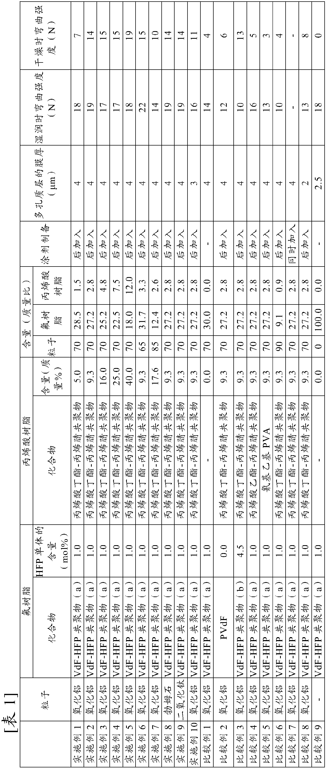
[0177] A coating solution prepared such that the solid content concentration was 13% by mass and the mass ratio of alumina particles: vinylidene fluoride-hexafluoropropylene copolymer (a): acrylic resin was 70:27.2:2.8 was used, except that A battery separator was obtained in the same manner as in Example 1. The obtained battery separator was evaluated for powder fall and was favorable.


PUM

PropertyMeasurementUnit
thicknessaaaaaaaaaa
particle sizeaaaaaaaaaa

Abstract

It is the aim of the present inventors to provide a battery separator with excellent dry-time adhesion, which is a new problem resulting from an expected increase in battery size in the future, and wet-time adhesion, without deterioration in air impermeability. The battery separator is provided with a microporous membrane and a porous layer disposed at least on one side of the microporous membrane, wherein the porous layer includes vinylidene fluoride-hexafluoropropylene copolymer and acrylic resin, the vinylidene fluoride-hexafluoropropylene copolymer includes a monomer unit with a hydrophilic group and 0.3 mole% or more and 3 mole% or less of a hexafluoropropylene monomer unit, and the acrylic resin includes a butylacrylate monomer unit.

Description

technical field [0001] The present invention relates to separators for batteries. Background technique [0002] Separators for batteries are required to have mechanical strength, heat resistance, ion permeability, pore blocking properties (shutdown properties), melting membrane rupture properties (meltdown properties), and the like. Therefore, the use of a battery separator provided with a porous membrane and a porous layer on the surface thereof has been studied so far. In addition, there has been a problem in recent years that the internal resistance of the battery increases and the cycle characteristics of the battery deteriorate due to partial separation of the interface between the separator and the electrode (caused by unevenness of the electrode surface or expansion / shrinkage of the electrode accompanying charging and discharging). Therefore, the separator is required to have good adhesion to the electrode (hereinafter referred to as wet adhesion) in the battery (tha...

Claims


Application Information

Patent Timeline
Patent Type & Authority Applications(China)
IPC IPC(8): H01M2/16H01M50/403H01M50/406H01M50/443H01M50/451H01M50/457H01M50/491
CPCY02E60/10H01M50/403H01M50/406H01M50/457H01M50/451H01M50/491H01M50/443H01M50/446H01M50/426H01M50/42H01M50/449H01M50/489H01M50/463H01M50/431H01M50/417Y02P70/50
Inventor 辻本润水野直树
Owner TORAY IND INC
Learn More