
Flywheel cover drilling clamp

A technology for drilling jigs and flywheels, applied in clamping, manufacturing tools, supports, etc., can solve the problems of complex clamping process, uneven drilling, and high equipment cost of flywheel cover jigs, and achieve simple structure, low manufacturing cost, The effect of increasing the contact area

Active Publication Date: 2018-04-13
浙江黎盛新材料科技有限公司
View PDF6 Cites 0 Cited by
  • Summary
  • Abstract
  • Description
  • Claims
  • Application Information

AI Technical Summary

Problems solved by technology

[0005] The purpose of the present invention is to provide a flywheel cover drilling jig to solve the problems of complex clamping process of the flywheel cover fixture, high equipment cost and uneven drilling, and realize the drilling of the side of the flywheel cover

Method used


Image

  • Flywheel cover drilling clamp
  • Flywheel cover drilling clamp

Examples


Embodiment 1

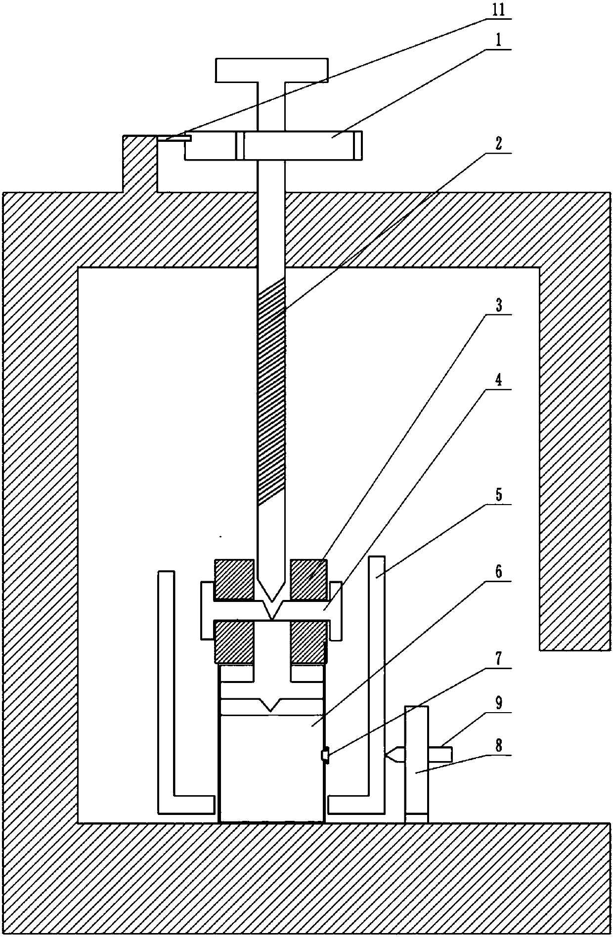
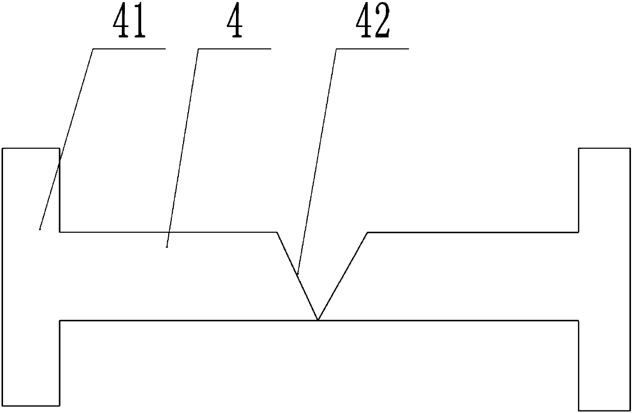
[0019] like figure 1 and figure 2 As shown, a flywheel cover drilling jig includes a cuboid frame, the top surface of the frame is rotatably connected with a vertical threaded rod 2, the upper end of the threaded rod 2 is a free end, the lower end of the threaded rod 2 is provided with a spike, and the threaded rod 2 The free end is provided with a rotating handle, and the threaded rod 2 is coaxially connected with a ratchet 1, and the ratchet 1 is located on the top surface of the frame, and the top surface of the frame is rotatably connected with a pawl 11, and the ratchet 1 and the pawl 11 are engaged; A clamping ring 3 is threadedly connected, and the lower end of the clamping ring 3 is symmetrically provided with two through holes along the central axis of the clamping ring 3, and a tension rod 4 is slidingly connected in the through hole, and one end of the tension rod 4 is provided with a wedge-shaped surface 42 , the other end of the tension rod is fixedly connected ...


PUM


Abstract

The invention belongs to the field of automobile accessory machining, and particularly discloses a flywheel cover drilling clamp. The flywheel cover drilling clamp comprises a cuboid machine frame, wherein a pawl and a vertical threaded rod are rotationally connected to the top surface of the machine frame, a sharp thorn part is arranged at the lower end of the threaded rod, the upper end of the threaded rod is a free end, a ratchet wheel is coaxially connected to the threaded rod, the ratchet wheel is located on the upper surface of the machine frame, and the pawl is meshed with the ratchet wheel. The threaded rod is in threaded connection with a clamping ring, two through holes are symmetrically formed in the side wall of the clamping ring along the central axis of the clamping ring, tensioning rods are connected into the two through holes in a sliding mode, wedge-shaped surfaces are arranged at one ends of the tensioning rods, the other ends of the tensioning rods are fixedly connected with tensioning blocks, and the wedge-shaped surfaces are matched with the sharp thorn part of the threaded rod. An air cylinder is fixedly installed on the bottom surface of the machine frame, the air cylinder is connected with the clamping ring in a buckling mode, an air blowing hole is formed in the side face of the air cylinder, the air blowing hole is provided with an air discharging plug, and the air discharging plug is connected with the air cylinder through a spring. Compared with the prior art, the flywheel cover drilling clamp is simple in structure, capable of punching holes uniformly, suitable for various types of flywheel covers, and high in applicability.

Description

technical field [0001] The invention belongs to the field of auto parts processing, and specifically discloses a drilling jig for a flywheel cover. Background technique [0002] The flywheel cover is one of the parts of the engine. The engine flywheel cover is located between the frame and the gearbox. The engine flywheel cover is installed on the outside of the engine flywheel and is fixedly connected with the engine frame and the gearbox. The flywheel cover is used for Covering the flywheel plays a role of safety protection, but during the drilling process of the flywheel cover, due to the certain curvature on the side of the flywheel cover, it is not easy to clamp. [0003] In the prior art, three-jaw chucks or pliers are often used to clamp and drill auto parts, but due to the arc surface, the contact surface between the pliers, the three-jaw chuck and the workpiece is small, so that the flywheel cover is easy to be removed from the pliers or three-jaw chuck. It will fa...

Claims


Application Information

Patent Timeline
Patent Type & Authority Applications(China)
IPC IPC(8): B23Q3/06B23Q11/00
CPCB23Q3/06B23Q11/005B23Q11/0064
Inventor 孙可均
Owner 浙江黎盛新材料科技有限公司
Learn More