A Method for Identifying Time Constant of Induction Motor Rotor

A rotor time constant, induction motor technology, applied in the control of generators, motor generator control, electronic commutation motor control and other directions, can solve problems such as system stability affecting observation accuracy, unsatisfactory identification effect, integral drift, etc.

Active Publication Date: 2019-08-09
XIAN UNIV OF SCI & TECH
View PDF4 Cites 0 Cited by
  • Summary
  • Abstract
  • Description
  • Claims
  • Application Information

AI Technical Summary

Problems solved by technology

The voltage model contains a pure integral link, which will introduce integral drift and DC bias problems in the process of estimating the rotational speed, resulting in unsatisfactory identification of the system at low speeds, and affecting the accuracy of observations and system stability

Method used


Image

  • A Method for Identifying Time Constant of Induction Motor Rotor
  • A Method for Identifying Time Constant of Induction Motor Rotor
  • A Method for Identifying Time Constant of Induction Motor Rotor

Examples


Embodiment Construction

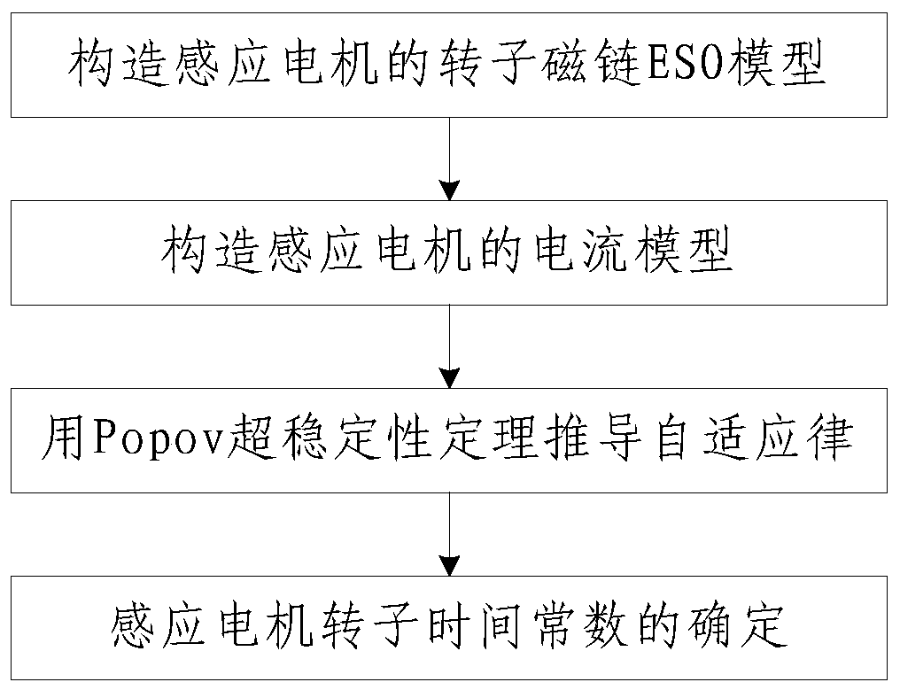
[0078] like figure 1 As shown, the induction motor rotor time constant identification method of the present invention includes the following steps:

[0079] Step 1, constructing the rotor flux linkage ESO (Extended State Observer, extended state observer) model of the induction motor;
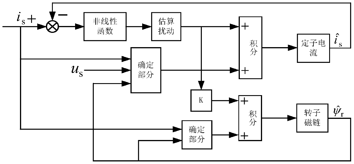
[0080] The basic idea of ​​ESO (Extended State Observer) is to construct a new system state based on a given input, and then send it to the original system through nonlinear function processing to obtain the expected output.

[0081] In this embodiment, the specific process of constructing the rotor flux ESO model of the induction motor in step 1 is:

[0082] Step 101. Under the two-phase stationary coordinate system, the stator current and rotor flux linkage of the induction motor are used as state variables, and the state equation of the induction motor is constructed as:

[0083]

[0084]

[0085]

[0086]

[0087] Among them, ψ rα is the α-phase rotor flux linkage in the two-...


PUM


Abstract

The invention discloses a method for identifying the rotor time constant of an induction motor, which comprises the steps of: 1. Constructing the ESO model of the rotor flux linkage of the induction motor; 2. Constructing the current model of the induction motor; ;4. Determination of the rotor time constant of the induction motor: with the rotor flux ESO model as the reference model and the current model as the adjustable model, under the action of the adaptive law, the reciprocal of the rotor time constant is estimated And send it into the current model, adjust the output flux value of the current model in real time, so that the output flux value of the current model can keep up with the flux output of the rotor flux ESO model, when the rotor flux ESO model and the current model output the rotor flux value equal, Determine the output value as the induction motor rotor time constant. The invention has accurate rotor time constant identification, can improve the precision of magnetic field orientation and speed tracking of the induction motor vector control system, has strong robustness to motor load disturbance, and has high motor speed tracking precision.

Description

technical field [0001] The invention relates to the technical field of motor control, in particular to a method for identifying the rotor time constant of an induction motor. Background technique [0002] The vector control technology can realize the decoupling control of torque and excitation, so that the AC motor can achieve the speed regulation performance similar to that of the DC motor. In the vector control system, accurate magnetic field orientation is essential, and an important factor affecting the magnetic field orientation is the accuracy of rotor parameters. When the motor works for a long time, the rotor resistance will increase with the increase of temperature, and the maximum change can reach more than 50%. The rotor inductance value will change with the magnetic saturation state, and the change value and the degree of magnetic saturation are nonlinear Therefore, the rotor time constant will change with the working state of the motor. When the rotor time con...

Claims


Application Information

Patent Timeline
Patent Type & Authority Patents(China)
IPC IPC(8): H02P21/00H02P21/16
CPCH02P21/0017H02P21/16
Inventor 贺虎成牛春光柳彦钊王文婷师磊刘洽孙磊
Owner XIAN UNIV OF SCI & TECH
Why Eureka
Try Eureka