
Lighting system for a motor vehicle

一种照明系统、车辆的技术,应用在照明系统领域,能够解决不能提供低分辨率系统照明特性、难以实现DMD系统视觉质量等问题,达到提高可见性和响应、改善可读性、高精度的效果

Inactive Publication Date: 2018-04-06
VALEO VISION SA
View PDF6 Cites 10 Cited by
  • Summary
  • Abstract
  • Description
  • Claims
  • Application Information

AI Technical Summary

Problems solved by technology

Existing high-resolution systems cannot provide the lighting characteristics of low-resolution systems, and it is difficult for low-resolution systems to achieve the visual quality of DMD systems

Method used


Image

  • Lighting system for a motor vehicle
  • Lighting system for a motor vehicle
  • Lighting system for a motor vehicle

Examples


Embodiment Construction

[0040] In the following description, similar reference numerals will be used to describe similar concepts based on different embodiments of the present invention.

[0041] Unless stated otherwise, technical features described in detail for a given embodiment may be combined with technical features described in the context of other embodiments described by way of example and not limitation.

[0042] In general, light emitting diode (also commonly referred to as LED) type light sources may be used with the present invention. It is worth noting that these LEDs can be equipped with at least one chip capable of emitting light, the intensity of which is advantageously adjustable according to the lighting and / or signaling function to be provided. There may be multiple light sources, as described more fully below. Furthermore, the term "light source" is here taken to mean a group of at least one elementary light source (e.g. LED) capable of producing an output light beam resulting in...


PUM


Abstract

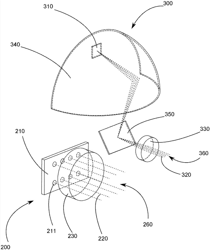
The present invention relates to an illumination system for a vehicle, including at least a first projection device for projecting at least one pixelated light source defining at least a first projection envelope and at least a second projection device for projecting at least one pixelated light beam defining at least a second projection envelope and configured to project at least one pictogram, wherein at least a first projection envelope and the at least a second projection envelope have at least one area of overlap.

Description

technical field [0001] The invention particularly relates to lighting systems. A preferred application relates to the automotive industry, for vehicle equipment, in particular for the provision of devices capable of emitting generally regulated light beams, also referred to as lighting functions. The emission of light beams in front of the vehicle is particularly practical. Background technique [0002] Hitherto, known lighting and signaling devices have been designed to emit, for example, low beams, high beams, lighting beams for fog and signaling beams. [0003] The dipped beam must provide good quality illumination and eliminate or reduce nuisance to surrounding vehicles caused by the generated light flux. Currently, dipped beam headlamps are basically designed for this, especially with a possibly complex cut-off at the top of the beam, in order to precisely limit or prevent illumination above the horizon and in an optimal way Prohibited light projection areas are desi...

Claims


Application Information

Patent Timeline
Patent Type & Authority Applications(China)
IPC IPC(8): F21S41/25F21S41/141
CPCB60Q1/0076B60Q1/04B60Q1/14B60Q1/143B60Q1/1438B60Q1/18B60Q1/2607B60Q1/34B60Q1/50F21S41/153F21S41/36F21S41/663F21S41/675G03B21/008F21S41/365B60Q2300/114B60Q2300/312B60Q2300/314B60Q2300/41B60Q2300/42B60Q2300/45B60Q2400/50B60Q1/545
Inventor 泽维尔·莫雷尔罗伟成
Owner VALEO VISION SA
Learn More