
Laser sintering scanning method

A scanning method and laser sintering technology, applied in the field of metal additive manufacturing, can solve problems such as cracking, detachment from the substrate, and scrapping of parts that fail to print, and achieve the effect of taking into account scanning efficiency and reducing thermal stress concentration

Inactive Publication Date: 2018-04-06
PANZHIHUA IRON & STEEL RES INST OF PANGANG GROUP
View PDF8 Cites 16 Cited by
  • Summary
  • Abstract
  • Description
  • Claims
  • Application Information

AI Technical Summary

Problems solved by technology

[0006] The invention provides a scanning method for laser sintering, which aims to solve the problem of the concentration of heat distribution in the area scanned by the laser in a certain direction during the selective laser melting process, and it is easy to form a large temperature gradient with the powder not scanned by the laser in the other direction. Under the action of stress, it is easy to cause detachment from the substrate, warping deformation, and cracking, resulting in the failure of printing parts to be scrapped.

Method used


Image

  • Laser sintering scanning method
  • Laser sintering scanning method
  • Laser sintering scanning method

Examples


Embodiment

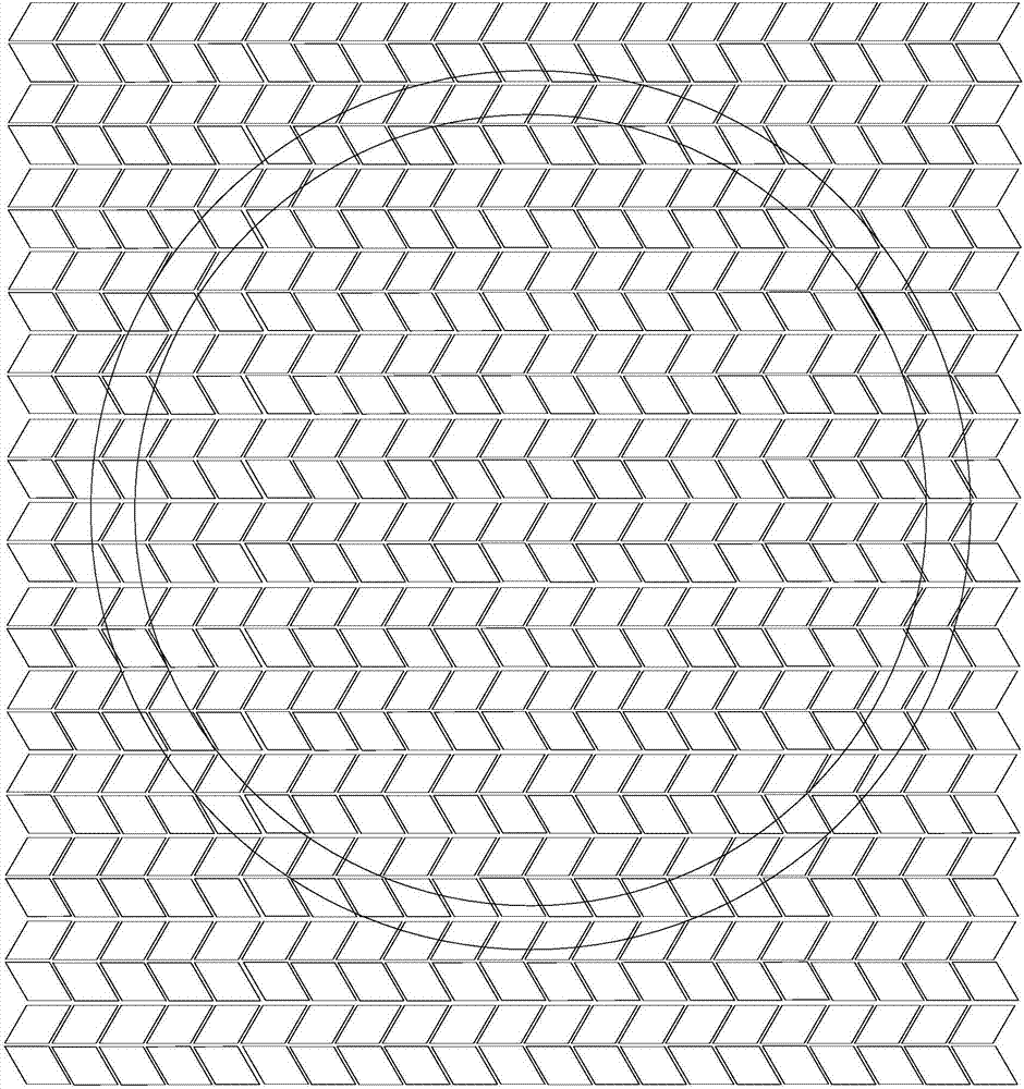
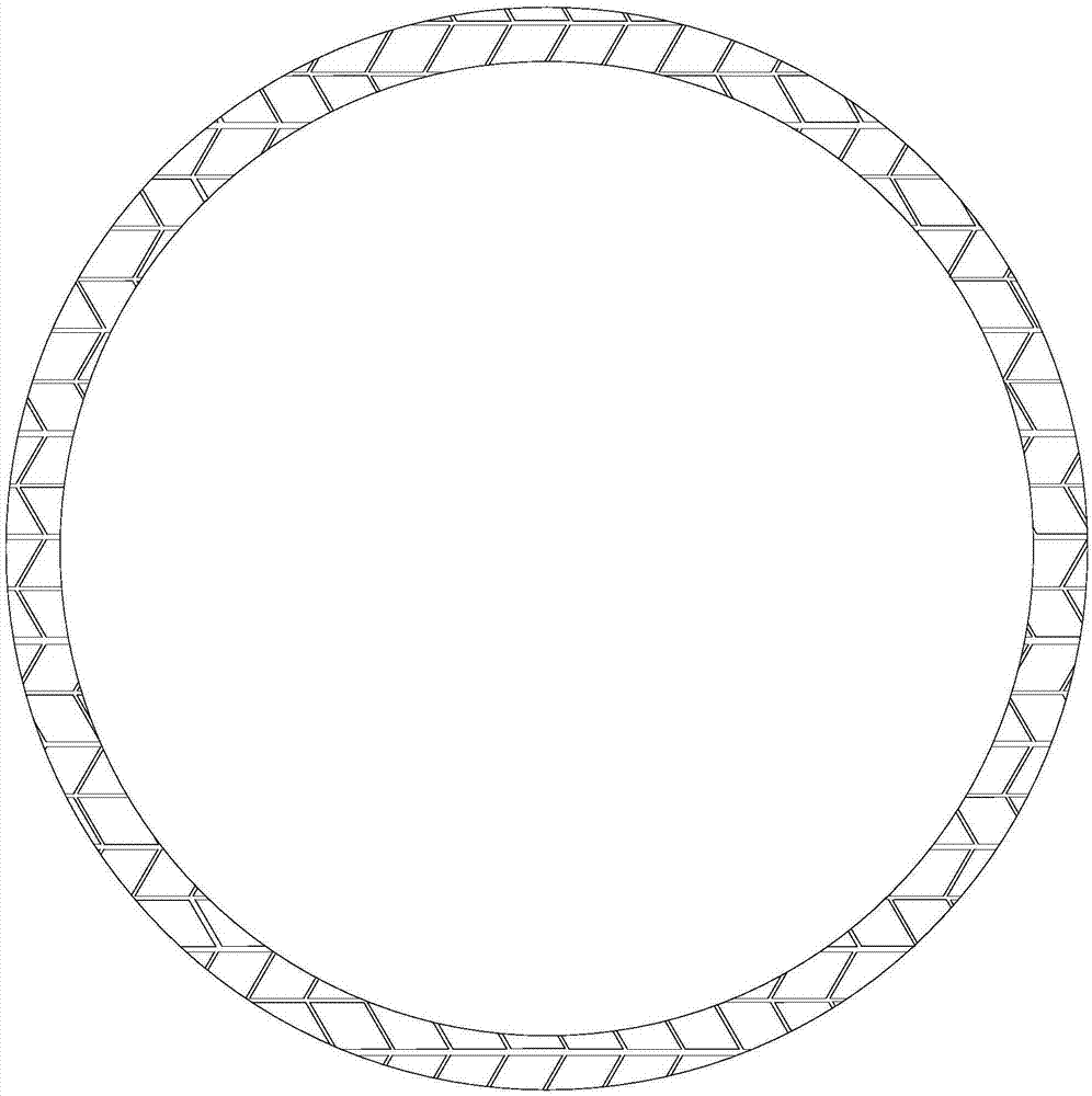
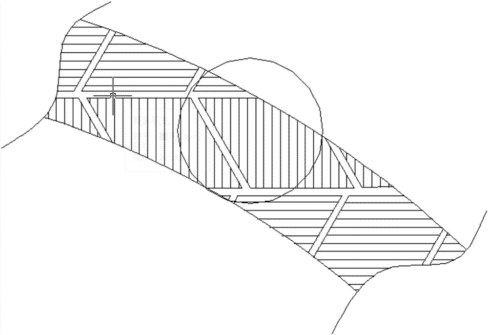
[0047] In this embodiment, the workpiece to be manufactured has a maximum cross-sectional diameter of For a circular thin-walled part with a wall thickness of 10mm, according to the cross-sectional information of the workpiece, the workpiece area is first divided into several partitioned graphics, and the partitioned graphics are grid-like parallelograms or irregular graphics with a side length of 10mm. The gap H between adjacent partition patterns takes a positive value of 0.7mm.

[0048] The laser sintering scanning method adopted in this embodiment includes the following main steps:

[0049] Step 1: Treat the irregular graphics of the boundary in the partition as a partition parallelogram, and then according to the shape and size of the workpiece, start with the partition graphics on one side of the workpiece, and sequentially scan the partition graphics that are parallel to each other continuous scan;

[0050] Step 2: Then use the infrared thermal imager to collect the ...


PUM


Abstract

The invention belongs to the technical field of metal additive manufacturing and particularly relates to a laser sintering scanning method mainly comprising division of the section of a workpiece, planning of the scanning direction, the first time of scanning, division after scanning according to temperatures, scanning according to temperature areas and other steps. According to the laser sintering scanning method, parallelogram division is conducted on the laser scanning section of the workpiece, then the temperature image of the sintering layer obtained after laser scanning is collected in real time through a thermal infrared imager, the outlines of the different temperature areas are extracted, adaptive scanning intervals are adopted for the low temperature areas and the high temperature areas in real time to form a scanning path, the problems that a large temperature gradient is formed due to temperature concentration of a certain area of a large-size thin-wall part, and residual stress is high are solved, the scanning efficiency is improved, and compactness and precision of the workpiece are ensured.

Description

technical field [0001] The invention belongs to the technical field of metal additive manufacturing, and in particular relates to a laser sintering scanning method for selective laser melting technology of large-scale thin-walled metal parts. Background technique [0002] Selective laser melting technology is a rapid manufacturing technology that scans layer by layer by controlling laser, and superimposes layers to form three-dimensional workpieces. Scanning path planning is an important part of 3D printing data processing, which has a great impact on the accuracy and physical properties of the formed parts. Choosing a reasonable scanning path can greatly improve the processing speed and the stability of the scanning mechanism. In addition, it can also effectively Minimize the number of starts and stops during the forming process. [0003] Some metal parts have the characteristics of large size and thin wall. Especially in the early stage of printing, due to the large suppo...

Claims


Application Information

Patent Timeline
IPC IPC(8): B22F3/105B33Y10/00B33Y50/02
CPCB33Y10/00B33Y50/02B22F10/00B22F10/366B22F10/28Y02P10/25
Inventor 黄云卢东钟兵毛凤娇
Owner PANZHIHUA IRON & STEEL RES INST OF PANGANG GROUP
Learn More