
Protecting die for double-glass assembly

A technology of double-glass components and molds, which is applied to electrical components, semiconductor devices, lamination, etc., can solve the problems of severe stress at the four corners, lack of glue at the four corners, and easy deformation of the glass, achieving a wide range of applications.

Pending Publication Date: 2018-04-03
天津环欧国际新能源科技有限公司
View PDF10 Cites 2 Cited by
  • Summary
  • Abstract
  • Description
  • Claims
  • Application Information

AI Technical Summary

Problems solved by technology

However, during the lamination process, the laminated silicone plate is a flexible material with a large amount of deformation, which produces a large pressure on the edge of the photovoltaic double-glass module. At the same time, the lamination temperature is high, and the glass is easily deformed when heated, resulting in blisters at the four corners of the photovoltaic double-glass module. , cannot be eliminated, seriously affecting the qualification rate of photovoltaic double-glass modules
[0003] Moreover, during the lamination process, the four corners are more stressed than other parts, which may easily lead to serious lack of glue at the four corners, affecting quality problems

Method used


Image

  • Protecting die for double-glass assembly
  • Protecting die for double-glass assembly
  • Protecting die for double-glass assembly

Examples


Embodiment 1

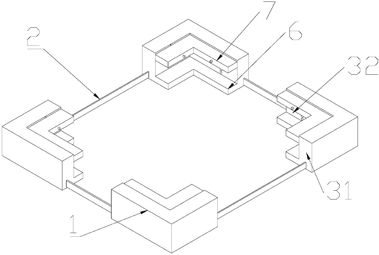
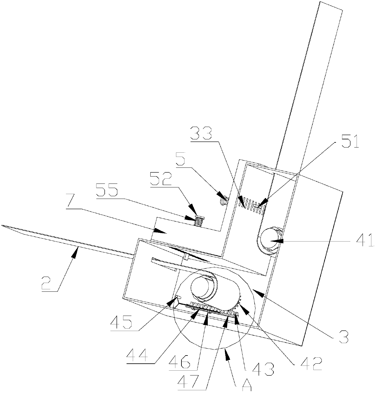
[0041] Embodiment 1, one end of the insertion rod 5 is connected to the inserting plate 51, the other end of the insertion rod 5 passes through the movable wing 7 to connect to the limit plate 52, the insertion rod 5 is sleeved with a buffer spring 55, and the buffer One end of the spring 55 is connected with the limiting plate 52 , and the other end of the buffer spring 55 is connected with the movable wing 7 . Squeeze the buffer spring 55 to completely penetrate the inserting plate 51 in the connecting hole 33, then turn the inserting rod 5 so that the inserting plate 51 crosses the connecting hole 33, loosen the inserting rod 5, and under the reset tension state of the buffer spring 55 , so that the movable wing 7 is fastened to the second side wall 32 of the cavity 3 .

Embodiment 2

[0042] Embodiment 2, one end of the insertion rod 5 is connected to the insertion plate 51, and the other end of the insertion rod 5 passes through the movable wing 7 to connect to the limit plate 52; the insertion rod 5 includes a front end rod 53 and a rear end rod 54, The diameter of the front end rod 53 connected with the flashboard 51 is set to be the same as the thickness of the flashboard 51 ; Turn the insertion rod 5 to make the rear end rod 54 and the movable wing 7 spirally move, so that the front end rod 53 extends out of the movable wing 7 to a longer length, so that the insertion plate 51 completely penetrates the connecting hole 33, and then rotate the insertion rod in the opposite direction 5. Make the movable flap 7 and the second side wall 32 seamlessly fastened, and the inserting plate 51 crosses the connection hole 33 .


PUM


Abstract

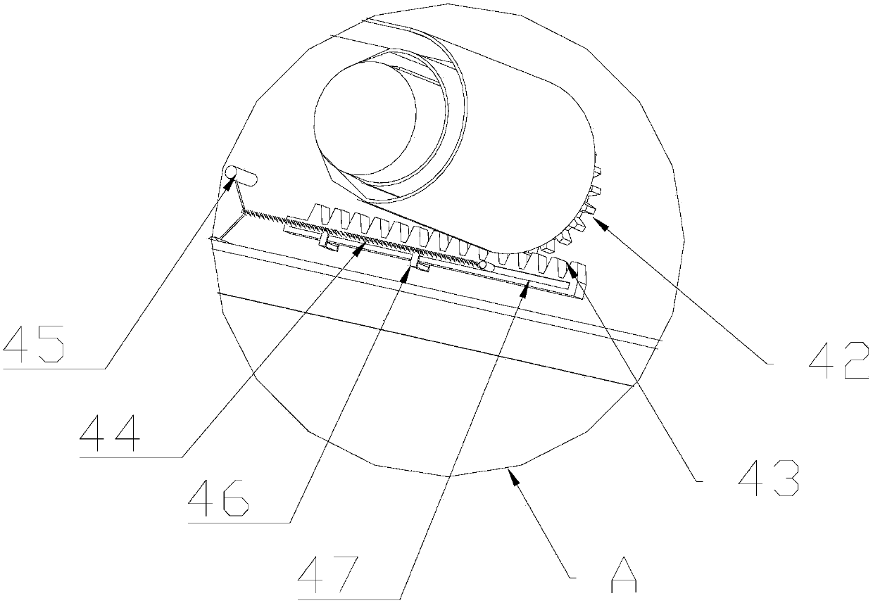
The invention provides a protecting die for a double-glass assembly. The protecting die comprises four thickness-adjustable protecting corners, and elastic strips which are connected between every twoadjacent protecting corners, wherein each protecting corner comprises a hollow cavity and an adjusting protecting wing; an elastic strip coiling part comprising a coiling shaft is arranged in each cavity; the coiling shafts are connected to two ends of the elastic strips which pass through first sidewalls of every two adjacent cavities; each adjusting protecting wing comprises a fixed protectingwing, and a movable protecting ring capable of adjusting the spacing relative to the fixed protecting wing; the movable protecting wings are movably connected to second sidewalls of the cavities. Theprotecting die is capable of protecting and stabilizing the double-layer glass assembly during laminating.

Description

technical field [0001] The invention belongs to the field of battery plate production, and in particular relates to four-corner protection equipment for battery plate processing. Background technique [0002] In the production process of photovoltaic double-glass modules, the lamination process is the most critical one. However, during the lamination process, the laminated silicone plate is a flexible material with a large amount of deformation, which produces a large pressure on the edge of the photovoltaic double-glass module. At the same time, the lamination temperature is high, and the glass is easily deformed when heated, resulting in blisters at the four corners of the photovoltaic double-glass module. , cannot be eliminated, seriously affecting the qualification rate of photovoltaic double-glass modules. [0003] Moreover, during the lamination process, the four corners are more stressed than other parts, which can easily lead to serious lack of glue at the four corn...

Claims


Application Information

Patent Timeline
IPC IPC(8): B32B37/00B32B38/18H01L31/18H01L31/048
CPCH01L31/0488H01L31/1876B32B37/0007B32B38/18Y02E10/50Y02P70/50
Inventor 李黎明蓝梓月宋广乔柳安琴
Owner 天津环欧国际新能源科技有限公司
Learn More