Target surface stray light illumination measurement device and measurement method

A measurement device and measurement method technology, applied in the field of laser projection, can solve the problems of inability to directly measure illuminance and difficulty in measurement, etc.

Active Publication Date: 2018-03-27
HISENSE
View PDF4 Cites 4 Cited by
  • Summary
  • Abstract
  • Description
  • Claims
  • Application Information

AI Technical Summary

Problems solved by technology

[0006] In the DLP projection system, due to the high illuminance of the stray light on the DMD target surface, the range of the sensor quickly reaches saturation, and it is impossible to directly measure the illuminance
Moreover, to measure the illuminance of the stray light on the DMD target surface, it needs to be measured during the working process of the DMD. Since the space of the DMD target surface is very small, it is difficult to measure

Method used


Image

  • Target surface stray light illumination measurement device and measurement method
  • Target surface stray light illumination measurement device and measurement method
  • Target surface stray light illumination measurement device and measurement method

Examples


Embodiment Construction

[0030] Typical embodiments that embody the features and advantages of the present invention will be described in detail in the following description. It should be understood that the present invention is capable of various changes in different embodiments without departing from the scope of the present invention, and that the description and illustrations therein are illustrative in nature and not limiting. this invention.

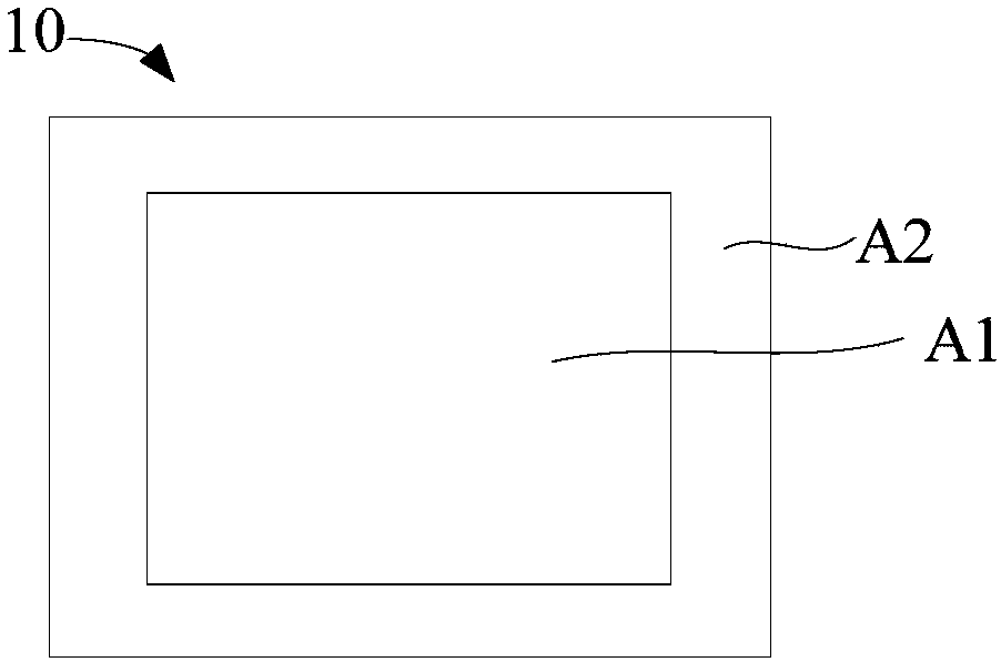
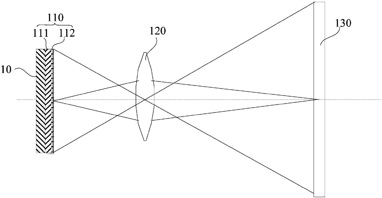
[0031] The invention provides a target surface stray light illumination measuring device. The target surface stray light illuminance measurement device of this embodiment can be used to measure the light of DMD chips in DLP (Digital Light Processing), LCD (Liquid Crystal Display) or LCOS (Liquid Crystal on Silicon) valve or light modulating element. Specifically, in this embodiment, the target surface stray light illumination measurement device is described by taking the illumination measurement of the target surface stray light of the DMD chip in the DL...


PUM


Abstract

The invention provides a target surface stray light illumination measurement device and measurement method. The target surface stray light illumination measurement device includes a diffuse reflectionboard, a projection lens, a measurement instrument and a controller. The diffuse reflection board includes a frame-shaped base board and a diffusion reflection layer. The base board is used for covering a non-action area of a light valve target surface. The diffuse reflection layer is arranged on the base board. The reflection property of the diffuse reflection layer meets requirements of a cosine irradiator. Stray light cast on to the diffuse reflection board is reflected to reflection light beams through diffuse reflection of the diffuse reflection layer. The reflection light beams form animage zone through projection via the projection lens. The measurement instrument is used for measuring the illumination of the stray light of the non-action area projected to the imaging zone. The controller calculates the target surface stray light illumination according to the area and the illumination of the imaging zone. According to the invention, measurement of target surface stray light illumination on optical valves such as a DMD and the like can be realized.

Description

technical field [0001] The invention relates to the field of laser projection, in particular to a target surface stray light illumination measurement device and a measurement method in a projection system. Background technique [0002] Projection display technology has been widely used in many fields such as home, business, education, engineering, etc. According to the different light modulation devices used, projection display technology can be divided into three technical architectures: digital light processing DLP (Digital Light Processing), liquid crystal display LCD (Liquid Crystal Display) and LCOS (Liquid Crystal on Silicon). Among them, DLP technology is the most widely used technical solution in the field of projection display, because the DLP technology architecture is easier to implement and lower in cost than LCD and LCOS architectures. In the DLP technology architecture, the digital micromirror DMD (Liquid Crystal on Silicon) chip of American TI Company is used...

Claims


Application Information

Patent Timeline
Patent Type & Authority Applications(China)
IPC IPC(8): G01J1/00G01J1/04
Inventor 郭帮辉
Owner HISENSE
Why Eureka
Try Eureka