Battery, electronic device and battery protection method
A battery and protection state technology, applied in battery circuit devices, secondary battery repair/maintenance, batteries, etc., can solve the problems of inconvenient use of batteries, the impact of batteries on the use range of electronic equipment, etc., to protect batteries and solve the problem of limited use scenarios , to meet the effect of detachable structure
- Summary
- Abstract
- Description
- Claims
- Application Information
AI Technical Summary
Problems solved by technology
Method used
Image
Examples
specific Embodiment
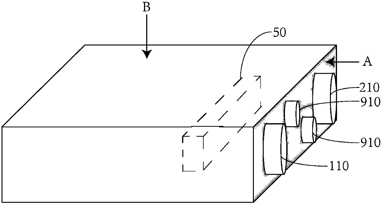
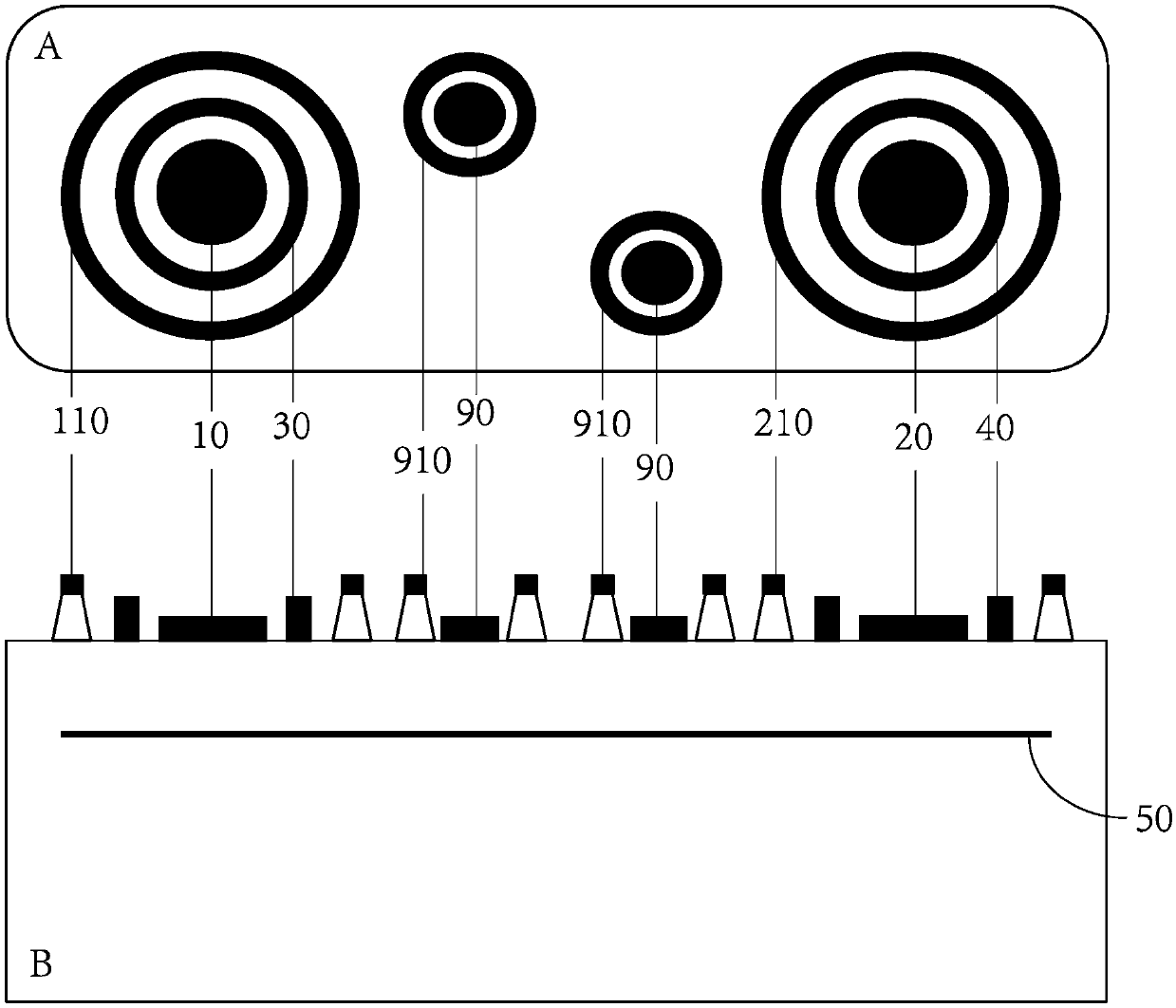
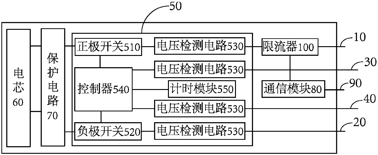
[0059] Please refer to the attached image below, figure 1 It is a schematic diagram of the three-dimensional structure of the battery provided by the first embodiment of the present invention; figure 2 It is the first embodiment of the present invention figure 1 The cross-sectional comparison diagram of battery end faces A and B; image 3 A structural block diagram of the battery provided in the first embodiment of the present invention; Figure 4 It is a schematic cross-sectional structure diagram of an electronic device provided in the second embodiment of the present invention; Figure 5 A flow chart of the battery protection method provided by the third embodiment of the present invention; Figure 6 Another flowchart of the battery protection method provided by the third embodiment of the present invention; Figure 7 Another flowchart of the battery protection method provided by the third embodiment of the present invention.
no. 1 example
[0061] Please refer to figure 1 , is a schematic diagram of the three-dimensional structure of the battery provided in the first embodiment of the present invention, combined with figure 2 , for the first embodiment of the invention figure 1 The cross-sectional comparison diagram of the battery end faces A and B, the battery includes a positive terminal 10 , a negative terminal 20 , a positive detection ring 30 , a negative detection ring 40 and a detection control unit 50 .
[0062] The positive terminal 10, the negative terminal 20, the positive detection ring 30 and the negative detection ring 40 are respectively arranged on the A end face of the battery; The terminal 10 surrounds it, and is separated from the positive terminal 10 by a distance, and an insulating material can also be arranged therebetween. The height of the positive detection ring 30 is higher than the height of the positive terminal 10; the negative detection ring 40 is a ring structure, and the negative...
no. 2 example
[0089] Please refer to Figure 4 , is a schematic cross-sectional structure diagram of an electronic device provided in the second embodiment of the present invention, the electronic device includes a host 1 , a battery compartment 2 and the battery 3 in the above first embodiment.
[0090] The battery compartment 2 is provided with a fixing structure 21 , and the fixing structure 21 is generally an elastic buckle structure, which can fix the battery 3 in the battery compartment 2 . The battery compartment 2 is provided with a first electrical connector 22 for electrical connection with the positive terminal 10 of the battery 3 ; the battery compartment 2 is provided with a second electrical connector 23 for electrical connection with the negative terminal 20 of the battery 3 . Here, the first electrical connector 22 and the second electrical connector 23 can be a shrapnel structure or a spring structure, one end of which is electrically connected to the positive terminal 10 o...
PUM
 Abstract
Description
Claims
Application Information
 - R&D Engineer
- R&D Manager
- IP Professional
- Industry Leading Data Capabilities
- Powerful AI technology
- Patent DNA Extraction
Browse by: Latest US Patents, China's latest patents, Technical Efficacy Thesaurus, Application Domain, Technology Topic, Popular Technical Reports.
© 2024 PatSnap. All rights reserved.Legal|Privacy policy|Modern Slavery Act Transparency Statement|Sitemap|About US| Contact US: help@patsnap.com


