
Preparation method for electrohydrodynamic jet deposition and laser cladding microtexture tool

A technology of laser cladding and micro-texture, which is applied in the coating process and coating of metal materials, can solve the problems of complex tool texture process and high cost, and achieve rapid and reliable solidification molding, small thermal deformation of materials, and texture structure. The effect of high precision

Inactive Publication Date: 2018-03-16
SHANDONG UNIV
View PDF7 Cites 13 Cited by
  • Summary
  • Abstract
  • Description
  • Claims
  • Application Information

AI Technical Summary

Problems solved by technology

However, there are problems such as complex process and high cost in the preparation of tool texture by this method.

Method used


Image

  • Preparation method for electrohydrodynamic jet deposition and laser cladding microtexture tool
  • Preparation method for electrohydrodynamic jet deposition and laser cladding microtexture tool
  • Preparation method for electrohydrodynamic jet deposition and laser cladding microtexture tool

Examples


example 1

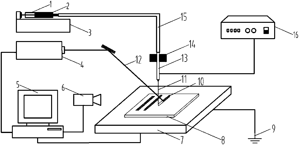
[0027] A preparation method of electro-jet deposition-laser cladding micro-textured tool, the base material is W18Cr4V high-speed steel tool, and the micro-textured material is Al 2 o 3 (its main component is 97% Al 2 o 3 , 2% Ni and 1% Al). It is characterized in that micro-texture is processed on the rake face of the tool. Concrete preparation process steps are as follows:

[0028] (1) Pretreatment of the tool substrate

[0029] The surface of the W18Cr4V high-speed steel tool was polished, and ultrasonically cleaned in acetone and absolute ethanol solutions for 20 min in order to remove the dirt on the tool surface.

[0030] (2) Electrojet deposition of microtexture

[0031] The computer 5 draws a three-dimensional model of the micro-texture, and uses the cross-sectional profile data and filling data of each layer of the three-dimensional model to generate the motion path and speed of the three-dimensional motion platform substrate 7 corresponding to the micro-texture...

example 2

[0036] A preparation method of electro-jet deposition-laser cladding micro-textured tool, the base material is W6Mo5Cr4V2 high-speed steel tool, the micro-textured material is hard alloy (the main components are 80% WC, 10% Co, 5% W, 1.5%VC, 1%Cr 3 C 2 and 1% Ni, 1% Al and 0.5% Mo). It is characterized in that micro-texture is processed on the rake face of the tool. Concrete preparation process steps are as follows:

[0037] (1) Pretreatment of the tool substrate

[0038] The surface of the W6Mo5Cr4V2 high-speed steel tool was polished, and then put into acetone and absolute ethanol solution for ultrasonic cleaning for 20 minutes to remove the dirt on the tool surface.

[0039] (2) Electrojet deposition of microtexture

[0040] The computer 5 draws a three-dimensional model of the micro-texture, and generates the motion path and speed of the three-dimensional motion platform substrate 7 corresponding to the micro-texture by using the cross-sectional profile data and filli...


PUM


Abstract

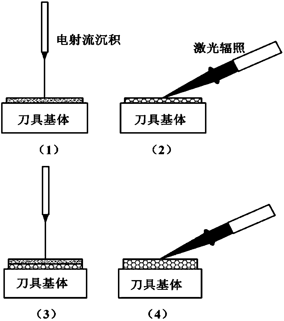
The invention belongs to the technical field of mechanical cutting tool manufacturing, and provides a preparation method for an electrohydrodynamic jet deposition and laser cladding microtexture tool.According to the preparation method, firstly, a certain pressure is applied to functional liquid to make the functional liquid flow out of the jet hole of a jet needle according to a certain flow; then, a certain of electric field is applied to the functional liquid to make the functional liquid form the fine jet flow with the diameter much less than the inner diameter of the jet hole, and the microtexture is formed on a tool matrix through jet deposition; and meanwhile, irradiation heat treatment on the deposited texture material with lasers so that the texture material can quickly solidify,shape up and be reliably fused with the tool matrix. The preparation method for an electrohydrodynamic jet deposition and laser cladding microtexture tool synthesizes the technical advantages of electrohydrodynamic jet deposition and laser machining, and has the advantages of being high in texture formation accuracy and material adaptability, simple in machining technology, easy to control and the like.

Description

technical field [0001] The invention belongs to the technical field of mechanical cutting tool manufacturing, and relates to a preparation method of electric jet deposition-laser cladding micro-textured tool. Background technique [0002] Metal dry cutting processing technology has gradually become one of the research hotspots of green manufacturing because it avoids the use of a large amount of cutting fluid, thereby greatly reducing manufacturing costs and reducing environmental pollution. However, due to the lack of cooling and lubricating effect of cutting fluid, the cutting conditions of dry cutting processing are even harsher, and the requirements for cutting tools are more stringent. How to reduce the friction and wear of the tool and improve the cutting performance of the tool under the condition of no lubrication or minimal lubrication has become one of the problems to be solved urgently in dry cutting. [0003] Surface texturing technology is a method to improve t...

Claims


Application Information

Patent Timeline
IPC IPC(8): C23C24/10
CPCC23C24/103
Inventor 李学木邓建新段冉刘亚运
Owner SHANDONG UNIV
Learn More