Material falling device

A blanking device and hot forming technology, applied in forging/pressing/hammer devices, metal rolling, manufacturing tools, etc., can solve the problems of insufficient machining allowance, distortion of the receiving plate, insufficient surface hardness, etc. It is not easy to be deformed or failed by heat, high heat resistance and deformation resistance, and excellent spring steel performance.

Pending Publication Date: 2018-03-16
上海魁殊自动化科技有限公司
View PDF0 Cites 1 Cited by
  • Summary
  • Abstract
  • Description
  • Claims
  • Application Information

AI Technical Summary

Problems solved by technology

[0004] The main defect of the above-mentioned blanking device in use is: when the camshaft 4 falls from the slide part 1 on the material receiving part 2, since the camshaft 4 is still a high-temperature red-hot part, the surface does not have sufficient hardness, and it is easy to It directly collides with the material receiving plate of the material receiving part 2 to cause bump damage. These bump damage will affect the appearance of the parts and require additional subsequent grinding. In serious cases, the product will be scrapped due to insufficient follow-up processing allowance. On the one hand, it is also because the camshaft 4 is still a high-temperature red hot part. After falling onto the material receiving plate of the material receiving part 2, the parts and the material receiving plate have a large heat exchange area, and it is difficult to apply cooling means, and the material receiving plate is very large. Fast distortion and deformation, so it is easier to collide with the product, and needs to be replaced very frequently, which greatly increases the production cost

Method used


Image

  • Material falling device
  • Material falling device
  • Material falling device

Examples


Embodiment 1

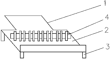
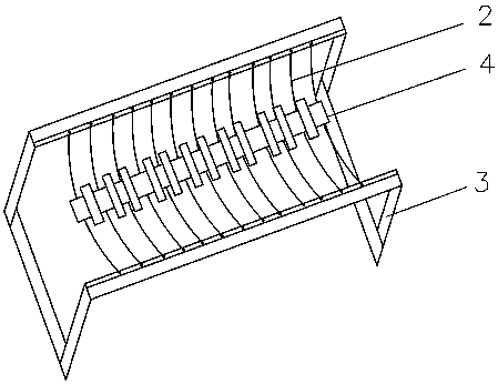
[0027] see figure 2 , figure 2 It is a blanking device of the present invention. The difference between this blanking device and Reference Document 1 is that the material receiving part 2 is no longer a material receiving plate, but metal wires arranged at intervals. This arrangement at least plays the following roles: Firstly, the contact area between the camshaft 4 and the metal wire is small, and the metal wire is smooth throughout, which avoids collision and collision with the camshaft. Risk of flying out of the splice 2.

Embodiment 2

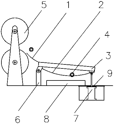
[0029] see image 3 , image 3 It is a more specific application of a blanking device of the present invention on a cross wedge rolling production line,

[0030] The cross wedge rolling production line includes a cross wedge rolling mill 5. The blanking device is integrally arranged at the blanking front end of the cross wedge rolling mill 5. The slide plate part 1 of the blanking device extends into the forming part of the camshaft 4 between the two rollers of the cross wedge rolling mill 5. The slide part 1 of the blanking device is connected to one end of the bracket 3 close to the cross wedge rolling mill 5, and the connection method is welding. In order to make the camshaft 4 and the slide part 1 form a sufficient buffer, the slide plate of the slide part 1 is designed as an arc Structure, the bottom of the end close to the cross wedge rolling mill 5 of the support 3 is hinged together with the ground support 6 arranged on the ground through the hinge frame, and the bott...

Embodiment 3

[0036] A blanking device of the present invention, such as the mechanical connection structure and transmission device described in Embodiment 1 and Embodiment 2, is easy to understand, and it achieves higher production efficiency through simple actions, and is an essential part of the present invention In the link, the material selection, manufacture and installation of the metal wire are very critical technologies.

[0037] Through continuous trial and error, the Ni-based alloy with the weight percent content of Fe finally selected between 10%-16% is used as the wire material of the present application. Ni-based alloy is a relatively good high-strength heat-resistant alloy with a reasonable formula The Ni-based alloy wire can be made to exhibit high heat resistance and deformation resistance. Preferably, the Ni-based alloy with a Fe content between 10% and 16% by weight also includes the following components (percentage by weight): 15- 20% Cr, 0.5-2% Al, 2.5-3% Mo, 0-1.2% W,...


PUM

PropertyMeasurementUnit
Diameteraaaaaaaaaa

Abstract

The invention relates to a material falling device, which is used for receiving heat forming parts in the metal heat processing process. The material falling device comprises a material collecting part and a support frame, wherein the material collecting part is formed by metal wires arranged at intervals; the metal wires are made of Ni-based alloys with the Fe content (weight percentage) being 10to 16 percent; the heat forming part is a cam shaft; the metal heat processing is wedge transverse milling processing. The material falling device also comprises a slide plate part, wherein the slideplate part is connected with one end, near a wedge transverse milling machine, of the support frame; the bottom of one end, near the wedge transverse milling machine, of the support frame is hinged to a ground supporter arranged on the ground through a hinging frame; the bottom of one end, far away from the wedge transverse milling machine, of the support frame is hinged to the end part of a piston rod of a lifting cylinder through a hinging block; a cooling groove is put in the bottom of the support frame; cooling water is contained in the cooling groove.

Description

technical field [0001] The invention relates to the field of mechanical equipment, in particular to a blanking device, which can be used in forging or rolling production lines to prevent bumps on product surfaces. Background technique [0002] Both forging and rolling are commonly used processes for thermal processing of metal profiles. Forging is to use impact force or pressure to deform the metal between the iron or forging die, so as to obtain forgings of the required shape and size. Rolling is to pass the metal blank through a For the gap (various shapes) of rotating rolls, due to the compression of the rolls, the material section is reduced and the length is increased. The pressure processing method, forging and rolling are all important forming methods of metal parts, which can ensure that metal parts have Good mechanical properties to meet the requirements of use. [0003] Products formed on forging equipment (hammers, presses, etc.) figure 1 It is a blanking devi...

Claims


Application Information

Patent Timeline
IPC IPC(8): B21B39/00B21J13/08C22C19/05C22C30/00
CPCC22C19/056C22C30/00B21B39/00B21J13/08
Inventor 王锐
Owner 上海魁殊自动化科技有限公司
Why Eureka
Try Eureka