Air duct variable radiator

A variable, radiator technology, used in cooling/ventilation/heating transformation, electrical components, electrical equipment structural parts, etc. The effect of eliminating local eddy currents, improving heat dissipation efficiency and reducing power consumption

Active Publication Date: 2020-03-24
CHENGDU ZHIRONG ZHICHUANG INTPROP MANAGEMENT CO LTD
View PDF8 Cites 0 Cited by
  • Summary
  • Abstract
  • Description
  • Claims
  • Application Information

AI Technical Summary

Problems solved by technology

[0005] The purpose of the present invention is to provide a variable air duct radiator to solve the problem that the air duct of the cooling fan connected to the router in the prior art cannot be changed, resulting in constant wind speed and constant air flow caused by the constant speed of the cooling fan blades. The direction cannot be changed, resulting in low heat dissipation efficiency and inflexible operation

Method used


Image

  • Air duct variable radiator
  • Air duct variable radiator
  • Air duct variable radiator

Examples


Embodiment 1

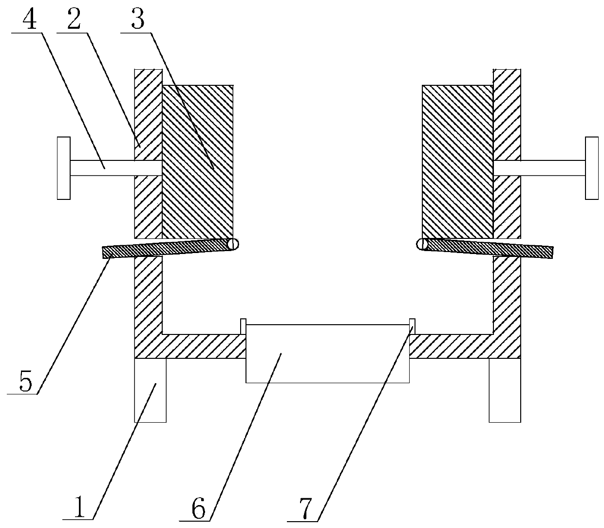
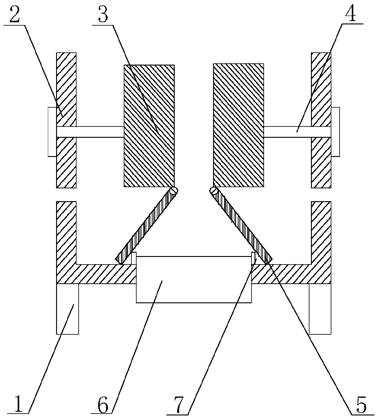
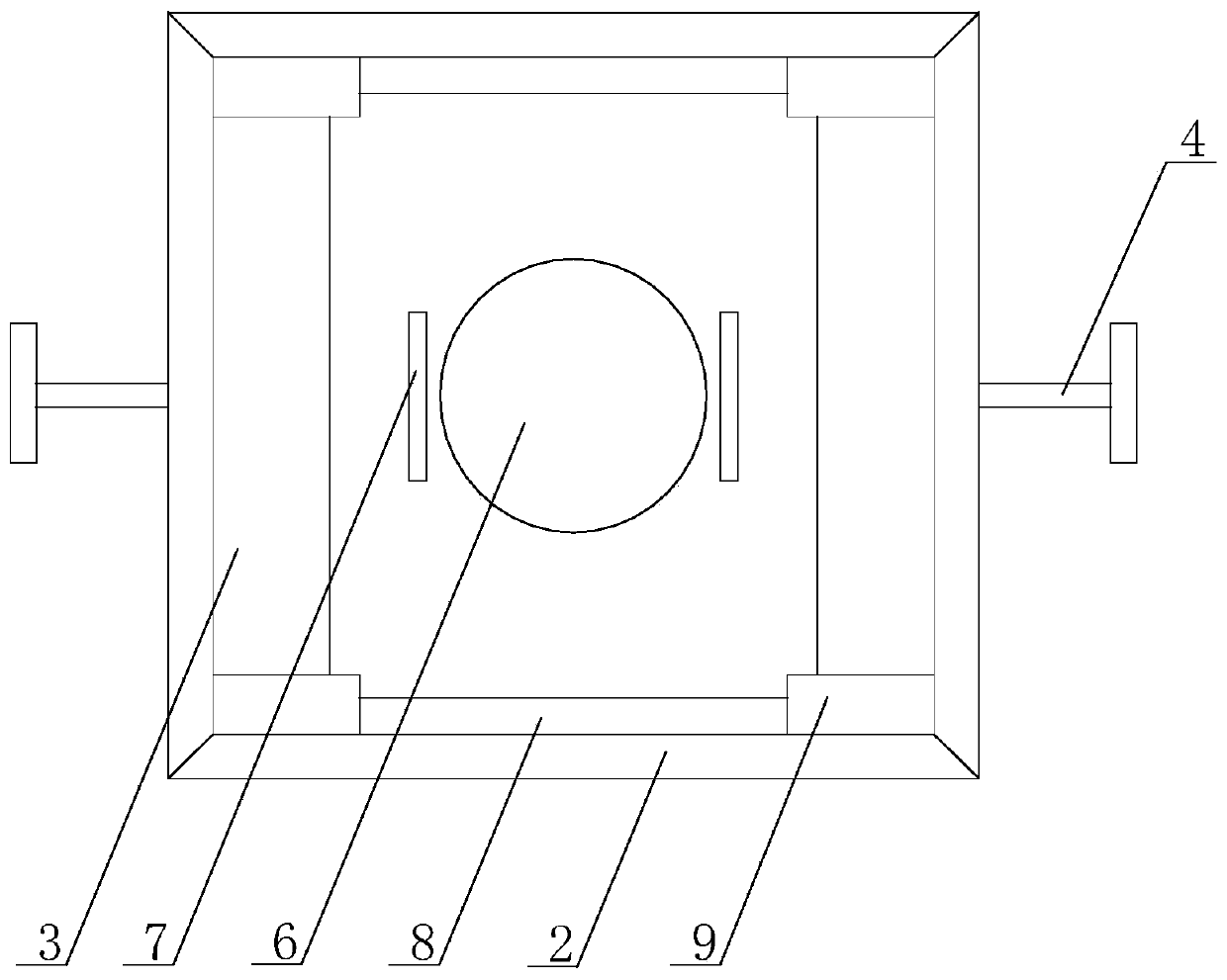
[0026] Such as Figure 1 to Figure 3 The air duct variable radiator shown in the figure includes a housing 2 with an upward opening, a supporting column 1 is arranged under the housing 2 , and a cooling fan 6 is arranged at the bottom of the housing 2 , and the air outlet of the cooling fan 6 is located inside the housing 2 , the two parallel inner walls of the housing 2 are provided with guide rails 8, the guide rails 8 are parallel to the horizontal plane, and also include two parallel moving plates 3, the moving plates 3 are located above the cooling fan 6, and the two ends of the moving plate 3 Both are fixed with a slider 9, the slider 9 is matched with the guide rail 8, the side of the moving plate 3 is fixed with an operating rod 4, and the operating rod 4 moves through the side of the housing 2 to the outside of the housing 2; the lower part of the moving plate 3 A rotating plate 5 is hinged on the surface; an elongated slot is provided on the inner wall of the housing...


PUM


Abstract

The present invention discloses a radiator with a variable air duct. The radiator comprises a shell body, wherein the opening of the shell body is upward. Supporting columns are arranged under the shell body, a cooling fan is arranged at the bottom of the shell body, the air outlet of the cooling fan is located in the shell body, guide rails are arranged on the two inner walls, parallel to each other, of the shell body, and the guide rails are parallel to the horizontal surface. The radiator also comprise two mobile plates parallel to each other, the mobile plates are located above the coolingfan, sliders are fixed on both ends of each mobile plate, the sliders are matched with the guide rails, and operating levers are fixed on the side of each mobile plate, wherein the operating levers pass through the sides of the shell body, and the operating levers can move to the outside of the shell body. According to the radiator, the user is allowed to control wind speed flexibly according toactual condition, as compared with the prior art of adjusting blade speed, the power consumption is reduced; meanwhile, the position of the air outlet between the mobile plates can also change, so that the centralized heat dissipation of some local position at the bottom of a router is realized, the heat dissipation efficiency is improved, and thus the expected heat dissipation effect is reached.

Description

technical field [0001] The invention relates to the field of heat dissipation machinery, in particular to a variable air duct radiator. Background technique [0002] In today's home or office, routers are an essential communication device. [0003] The router is usually turned on for a long time during use. When the ambient temperature is high, or after the router has been used for a long time, or when the router is partially faulty, the working temperature of the router may rise, so it is necessary to dissipate heat from the router. Reduce its working temperature to a suitable temperature to ensure that its electronic components operate at a suitable temperature and prolong the service life of the router. [0004] Existing heat dissipation devices mostly use heat dissipation fans to transfer heat from the surface of the router to the air by accelerating the air flow on the surface of the router, thereby reducing the operating temperature of the router. However, the air du...

Claims


Application Information

Patent Timeline
Patent Type & Authority Patents(China)
IPC IPC(8): H05K7/20
CPCH05K7/20145
Inventor 黄友华
Owner CHENGDU ZHIRONG ZHICHUANG INTPROP MANAGEMENT CO LTD
Why Eureka
Try Eureka