Communication equipment support structure based on heat dissipation mechanism

A technology of communication equipment and heat dissipation mechanism, which is applied to the structural parts of electrical equipment, cooling/ventilation/heating transformation, electrical components, etc. It can solve the problems of low heat dissipation efficiency, constant wind speed of cooling fan blades, and inflexible operation, etc. Effects of cooling efficiency, reducing power consumption, and eliminating local eddy currents

Active Publication Date: 2019-12-13
新沂国宏信息科技有限公司
View PDF8 Cites 0 Cited by
  • Summary
  • Abstract
  • Description
  • Claims
  • Application Information

AI Technical Summary

Problems solved by technology

[0005] The purpose of the present invention is to provide a support structure for communication equipment based on a heat dissipation mechanism, so as to solve the problem that the heat dissipation fan air duct provided on the router support in the prior art cannot be changed and the wind speed generated by the heat dissipation fan blade is constant. , and the direction of the flowing air cannot be changed, resulting in low heat dissipation efficiency and inflexible operation

Method used


Image

  • Communication equipment support structure based on heat dissipation mechanism
  • Communication equipment support structure based on heat dissipation mechanism
  • Communication equipment support structure based on heat dissipation mechanism

Examples


Embodiment 1

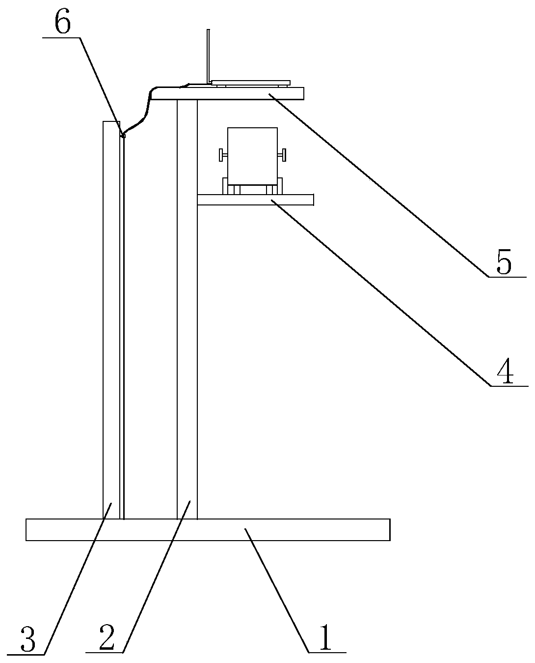
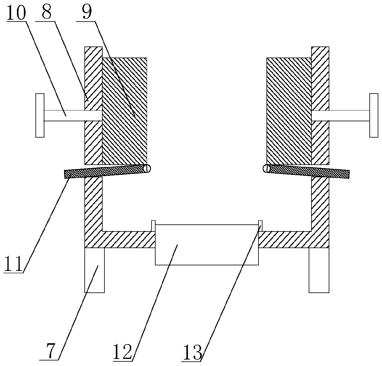
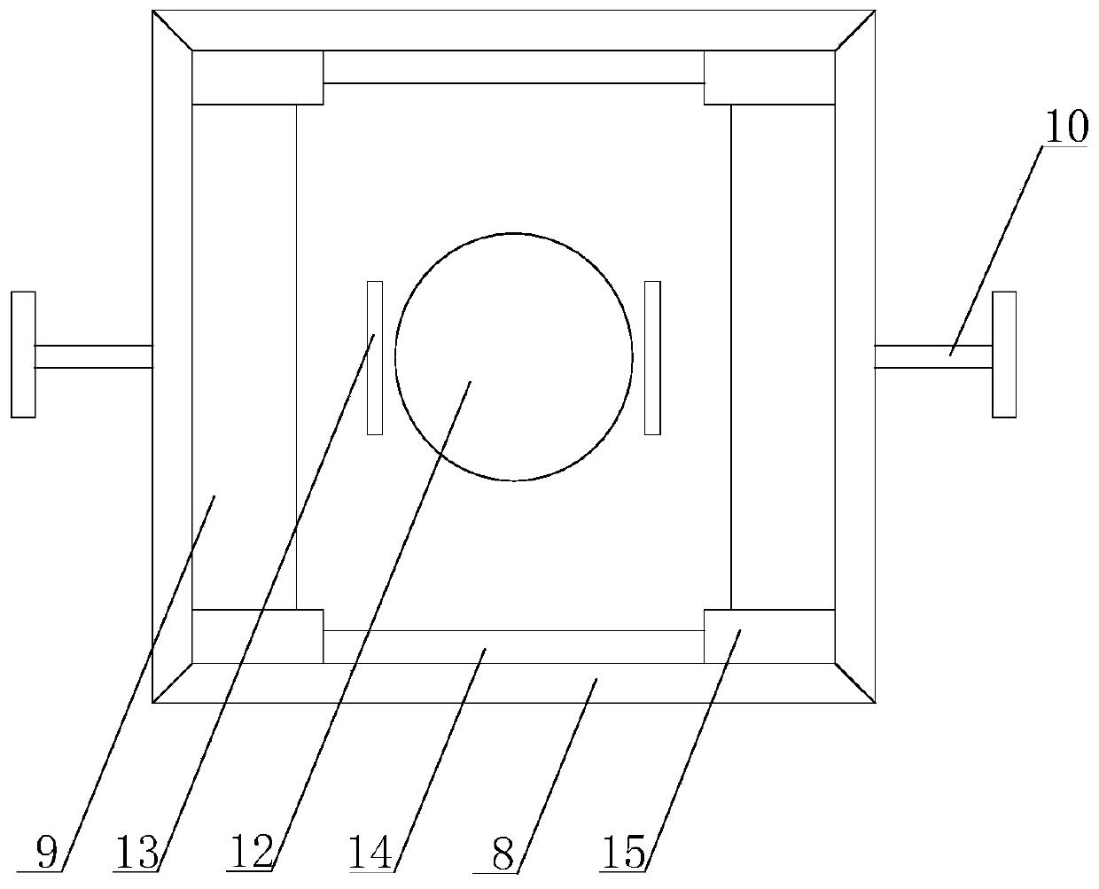
[0028] Such as Figure 1 to Figure 4 The communication equipment support structure based on the heat dissipation mechanism shown includes a bottom plate 1, a support frame 2 is fixed on the bottom plate 1, a placement platform 5 is fixed on the top of the support frame 2, and a number of ventilation openings are arranged on the placement platform 5. The support frame 2 A heat dissipation fan stand 4 located below the placement platform 5 is also installed on the top. A heat dissipation device is placed on the heat dissipation fan stand 4. The heat dissipation device includes a casing 8 with an upward opening, the opening is facing the air vent, and the bottom of the casing 8 is arranged There is a support column 7, and the support column 7 is fixed on the heat dissipation fan stand 4. The bottom of the housing 8 is provided with a heat dissipation fan 12. The air outlet of the heat dissipation fan 12 is located inside the housing 8, and the two sides of the housing 8 are parall...


PUM


Abstract

The invention discloses a heat dissipation mechanism-based communication equipment support structure, which comprises a bottom plate and movable plates, wherein a support frame is fixed on the bottomplate; a placement platform and a cooling fan station are arranged on the support frame; a heat dissipation device is arranged on the cooling fan station and comprises a shell with an upward opening,and the opening directly faces a ventilation opening; support columns are arranged at the lower part of the shell and are fixed on the cooling fan station; a cooling fan is arranged at the bottom of the shell; guide rails are arranged on the inner wall of the shell; slide blocks are fixed on each movable plate; an operating rod is fixed on the side surface of each movable plate and movably runs through the side surface of the shell to the outside of the shell; the lower surface of each movable plate is hinged with a rotating plate; and elongated placement grooves are formed in the inner wall of the shell and the widths of the placement grooves are equal to the thicknesses of the corresponding rotating plates. The heat dissipation device is capable of simply, flexibly and quickly changing the width of an air duct to change the air speed of the air duct, and is capable of changing the position of an air outlet to cool the local position.

Description

technical field [0001] The invention relates to the field of communication device auxiliary equipment, in particular to a communication equipment support structure based on a heat dissipation mechanism. Background technique [0002] In today's homes or offices, routers are an essential piece of communication equipment, and routers are usually set on dedicated router brackets. [0003] When the router is turned on for a long time during use, when the ambient temperature is high, or after the router has been used for a long time, or when the router is partially faulty, the working temperature of the router may rise. Lower to the right temperature to ensure its electronic components operate at the right temperature and prolong the service life of the router. [0004] The heat dissipation device installed on the existing router bracket mostly adopts a heat dissipation fan, and by accelerating the air flow on the surface of the router, the heat on the surface of the router is tr...

Claims


Application Information

Patent Timeline
Patent Type & Authority Patents(China)
IPC IPC(8): H05K7/20
CPCH05K7/20136
Inventor 黄友华
Owner 新沂国宏信息科技有限公司
Why Eureka
Try Eureka