Converter cooling device

A heat dissipation device and converter technology, applied in the direction of output power conversion device, conversion of AC power input to DC power output, conversion of equipment structural parts, etc., can solve the problem of low service life of heating components and heat dissipation capacity of heating components Poor problems, to achieve the effect of improving heat dissipation efficiency, increasing service life and reducing quantity

Active Publication Date: 2018-10-23
CRRC QINGDAO SIFANG ROLLING STOCK RES INST
View PDF6 Cites 0 Cited by
  • Summary
  • Abstract
  • Description
  • Claims
  • Application Information

AI Technical Summary

Problems solved by technology

[0005] The present invention aims at the above-mentioned technical problems that the heat dissipation device of the existing converter has poor heat dissipation capability for the heating components and the service life of the heating components is low, and proposes a heat dissipation device for the converter with high heat dissipation capability and prolonging the service life of the heating components

Method used


Image

  • Converter cooling device
  • Converter cooling device
  • Converter cooling device

Examples


Embodiment Construction

[0024] In the following, the present invention will be specifically described through exemplary embodiments. It should be understood, however, that elements, structures and characteristics of one embodiment may be beneficially incorporated in other embodiments without further recitation.

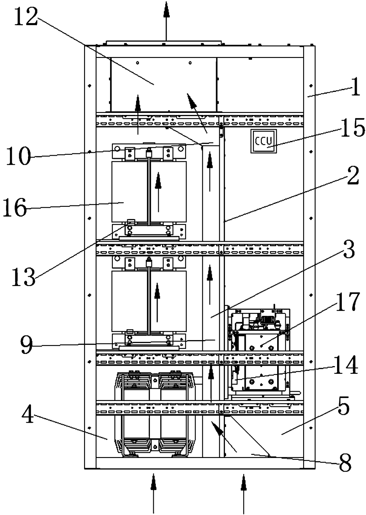
[0025] In the description of the present invention, it should be noted that the orientation or positional relationship indicated by the terms "inner", "outer", "upper", "lower", "front", "back" etc. are based on the attached figure 1 The positional relationship shown is only for the convenience of describing the present invention and simplifying the description, but does not indicate or imply that the referred device or element must have a specific orientation, be constructed and operated in a specific orientation, and therefore cannot be construed as limiting the present invention . In addition, the terms "first", "second", and "third" are used for descriptive purposes only, and should not...


PUM


Abstract

The present invention provides a current transformer heat radiation apparatus comprising a cabinet body, through which cooling wind can pass. The cabinet body is provided with a partition plate in the direction of passing of the cooling wind to separate the inside of the cabinet body into a first chamber in which an electric reactor can be mounted and a second chamber in which a power module can be mounted. The partition plate is connected to the power module in a sealed way. The partition plate is fixedly connected to one end, provided with an air inlet, of the cabinet body. The partition plate is connected to the inner wall of the cabinet body in a sealed way in the direction of the two ends perpendicular to the cooling wind flow direction. The two ends of the first chamber are respectively connected with the air inlet and an air outlet. The partition plate is provided with a vent hole connected with an air transmission duct and the second chamber. Cooling fins of the power module extend into the air transmission duct through the vent hole. The current transformer heat radiation apparatus of the invention has high heat radiation capability and longer heating components usage life.

Description

technical field [0001] The invention belongs to the technical field of converter cooling devices for rail transit, and in particular relates to a converter cooling device. Background technique [0002] The converter has the functions of inverter feedback, rectification and traction, and voltage stabilization. When it is used for ground power supply of urban rail transit, it can realize the conversion between AC and DC in the substation. The main heating components of the converter include self-power modules and reactors. In order to ensure the good performance of each component, it is necessary to dissipate heat from each heating component when the converter is working. [0003] However, the air duct design of the existing converter cooling device is to connect various heating components in series in the entire ventilation direction, so it is difficult to dissipate heat from different heating components separately, resulting in the air temperature gradually increasing along ...

Claims


Application Information

Patent Timeline
Patent Type & Authority Patents(China)
IPC IPC(8): H02M7/00H05K7/20
CPCH02M7/003H05K7/20145H05K7/20209
Inventor 史建强王长昌蔡纪卫徐先伟张德雨鲍庆臣韩国风
Owner CRRC QINGDAO SIFANG ROLLING STOCK RES INST
Why Eureka
Try Eureka