
Connecting structure of caisson and partition wall and construction method of connecting structure

A technology for connecting structures and construction methods, applied in the direction of walls, building components, building structures, etc., can solve the problems of high waterproof requirements, difficult to meet the waterproof requirements of toilets and adjacent rooms, etc., to improve the waterproof effect, enhance the application, The effect of increasing the space used

Pending Publication Date: 2018-03-13
CHANGSHA BROAD HOMES IND GRP CO LED
View PDF7 Cites 2 Cited by
  • Summary
  • Abstract
  • Description
  • Claims
  • Application Information

AI Technical Summary

Problems solved by technology

However, in some cases, there is no beam overlap on one side of the prefabricated toilet, and due to the use function of the toilet, the toilet and the main functional room need to be separated by a partition wall. The existing prefabricated toilet does not involve this kind of lap
Moreover, due to the high waterproof requirements of the bathroom, it is difficult to meet the waterproof requirements of the bathroom and adjacent rooms only by the waterproof structure and materials inside the caisson

Method used


Image

  • Connecting structure of caisson and partition wall and construction method of connecting structure
  • Connecting structure of caisson and partition wall and construction method of connecting structure
  • Connecting structure of caisson and partition wall and construction method of connecting structure

Examples


Embodiment Construction

[0022] The present invention will be described in further detail below in conjunction with the accompanying drawings.

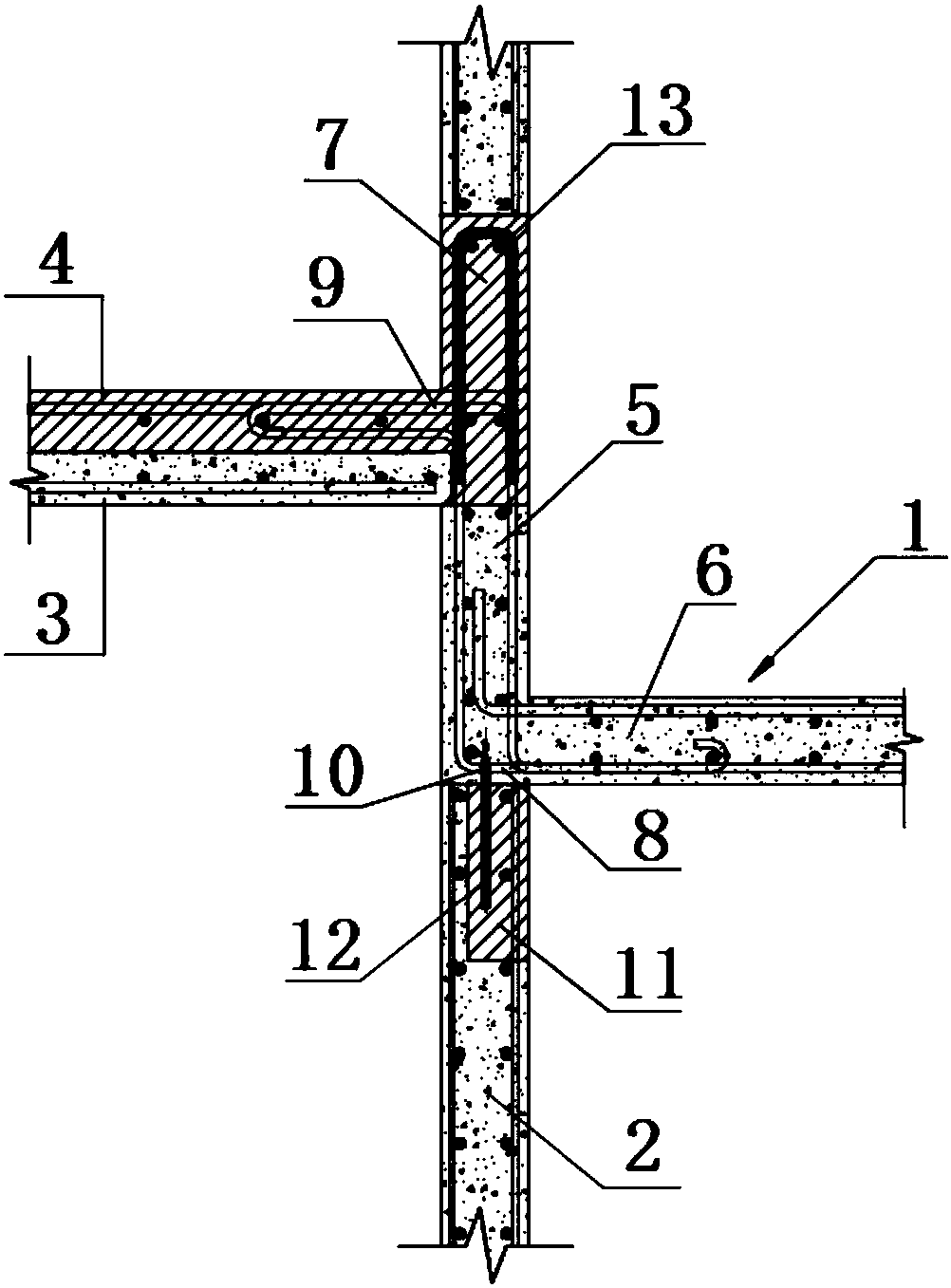
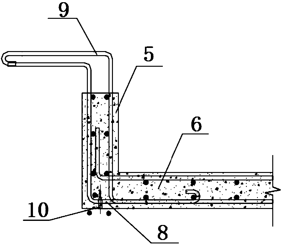
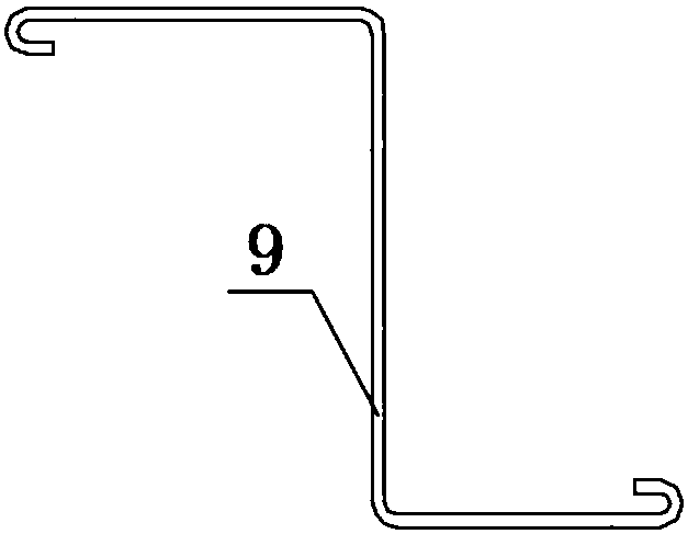
[0023] see Figure 1-2 The connection structure between the caisson and the partition wall includes a fully prefabricated caisson 1, a prefabricated partition wall 2 and a floor slab, the floor slab includes a prefabricated floor 3 and a cast-in-place floor 4, and the caisson 1 includes a side plate 5 and a bottom plate 6. The side plate 5 of the caisson 1 is in the same vertical plane as the prefabricated partition wall 2, and the end of the floor prefabricated layer 3 rests on the upper surface of the side plate 5 of the caisson 1, so A cast-in-place reverse sill 7 is provided above the floor in the vertical plane, and the cast-in-place reverse sill 7 and the floor slab cast-in-place layer 4 are integrally formed by cast-in-place, and the caisson 1 is also provided with a slab bottom Ribs 8 and additional slab gluten 9, the bottom slab 8 and the additional...


PUM

PropertyMeasurementUnit
Lengthaaaaaaaaaa

Abstract

The invention discloses a connecting structure of a caisson and a partition wall and a construction method of the connecting structure. The connecting structure is characterized in that the connectingstructure comprises the fully-prefabricated caisson, the prefabricated partition wall and a floor slab. The floor slab comprises a floor slab prefabricating layer and a floor slab cast-in-situ layer.The caisson comprises a side plate and a bottom plate. The side plate of the caisson is in the same vertical plane with the prefabricated partition wall. The end part of the floor slab prefabricatinglayer is placed on the upper surface of the side plate of the caisson. A cast-in-situ reverse ridge is arranged at the position, located in the vertical plane, above the floor slab. The cast-in-situreverse ridge and the floor slab cast-in-situ layer are one-batch formed through cast-in-situ. The caisson is internally provided with a plate bottom rib and an additional plate surface rib. The platebottom rib and the additional plate surface rib enter the floor slab cast-in-situ layer through a bending anchor. By means of the connecting structure, application of a toilet caisson structure in anassembled building is enhanced, the waterproof effect of the assembled toilet caisson is improved, the use space of a toilet is enlarged, and requirements of industrialized production can be met.

Description

technical field [0001] The invention relates to a connection structure between an assembled toilet caisson and a partition wall and a construction method thereof, belonging to the technical field of construction engineering. Background technique [0002] Existing prefabricated restroom adopts caisson approach, such as Patent Document 1 (CN204401783U) makes the restroom a whole prefabricated caisson, bends and anchors into the beam or the cast-in-place layer of the shear wall through the reserved bottom reinforcement and additional plate reinforcement , so that it can be poured into one. This kind of structural stress method adopts at least bilateral anchoring into beams or shear walls to ensure the structural safety of the toilet. However, in some cases, there is no beam overlap on one side of the prefabricated toilet, and due to the use function of the toilet, the toilet and the main functional room need to be separated by a partition wall. The existing prefabricated toile...

Claims


Application Information

Patent Timeline
IPC IPC(8): E04B1/38E04B2/74E04B5/17E04G21/00E04B1/66
CPCE04B1/38E04B1/66E04B2/74E04B5/17E04G21/00
Inventor 张剑熊育明李志强
Owner CHANGSHA BROAD HOMES IND GRP CO LED
Learn More