
Gas turbine intake air treatment system integrating pollutant cleaning, filtration and evaporative cooling

A technology of evaporative cooling and gas turbine, which is applied in the direction of combustion air/combustion-air treatment, gas turbine device, turbine/propulsion device inlet, etc. It can solve the problem of no evaporative cooling cleaning device, reduction of steam turbine output, low energy utilization rate, etc. problems, achieve the effect of reducing gas pollutants, improving output and efficiency, and prolonging life

Active Publication Date: 2019-07-30
ZHEJIANG UNIV
View PDF5 Cites 0 Cited by
  • Summary
  • Abstract
  • Description
  • Claims
  • Application Information

AI Technical Summary

Problems solved by technology

Since the exhaust heat of the gas turbine is used to concentrate and regenerate the solution of the solution dehumidifier instead of generating steam to expand and do work in the steam turbine, although the output of the gas turbine has increased, it has reduced the output of the steam turbine and the total cycle time On the contrary, the output decreased
At the same time, from using the gas turbine exhaust waste heat to generate hot water, to using hot water to concentrate and regenerate the solution dehumidifier, it involves multiple energy conversions, as well as heat dissipation and heat preservation of hot water pipes, so the energy utilization rate is relatively low
[0009] Similarly, there is no evaporative cooling and cleaning device in this patent document, and the intake air is not cleaned to remove dust, haze, and gas pollutants.

Method used


Image

  • Gas turbine intake air treatment system integrating pollutant cleaning, filtration and evaporative cooling
  • Gas turbine intake air treatment system integrating pollutant cleaning, filtration and evaporative cooling
  • Gas turbine intake air treatment system integrating pollutant cleaning, filtration and evaporative cooling

Examples


Embodiment

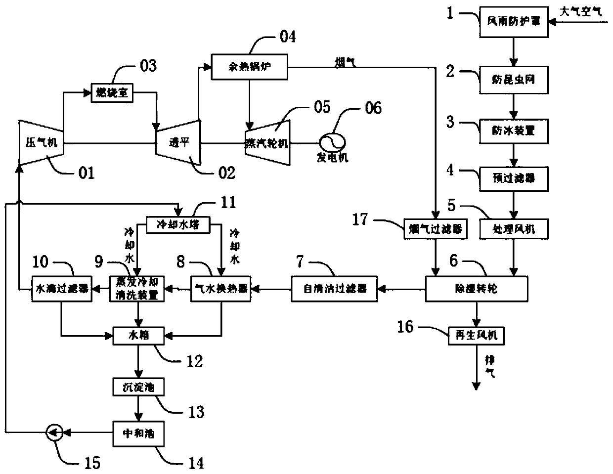
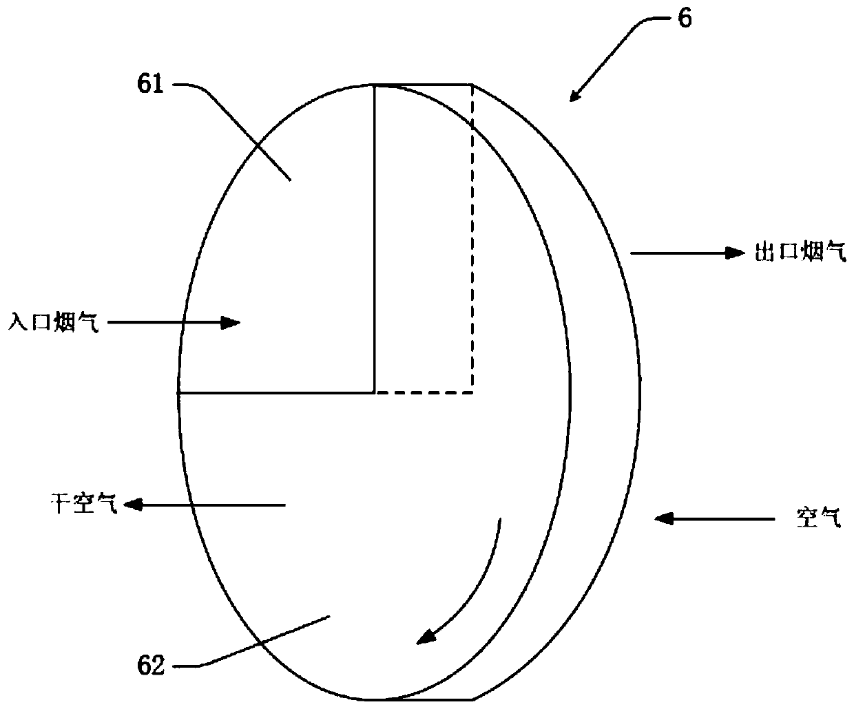
[0037] see figure 1 and figure 2 , the gas turbine air intake treatment system integrating pollutant cleaning, filtering and evaporative cooling is set at the intake end of the gas-steam combined cycle power unit composed of gas turbine, steam turbine 05, waste heat boiler 04 and generator 06. The gas turbine is composed of compressed gas The compressor 01, the combustion chamber 03 and the turbine 02 are composed of the gas-steam combined cycle power generation unit, and the intake end of the gas-steam combined cycle generator set is set on the compressor 01.

[0038] Inlet Cooling Improves Performance of Gas-Steam Combined Cycle Power Plants: Gas turbines are constant-volume mechanical power plants, and the mass flow of air depends on the air density. The air temperature at the inlet of the compressor decreases, the density increases, the mass flow rate of the air flowing through the gas turbine increases, and the working capacity of the gas turbine increases accordingly. ...


PUM


Abstract

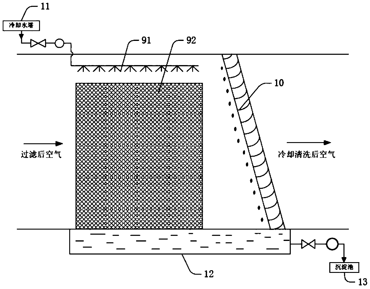
The invention discloses a gas turbine air inlet treatment system integrated with pollutant cleaning, filtering and evaporating cooling. The treatment system comprises an air filter device, a treatmentdraught fan, a dehumidifying rotating wheel, a self-cleaning filter, a gas and water heat exchanger, an evaporation cooling cleaning device and a water drop filter which are sequentially connected according to the air leading-in sequence; an outlet of the water drop filter is connected with an inlet of a gas compressor; a smoke filter is connected to a pipeline between a waste heat boiler and thedehumidifying rotating wheel; an outlet of the gas and water heat exchanger, the evaporation cooling cleaning device and the water drop filter is provided with a water circulation device for collecting returned water. Input gas of a gas turbine is subject to cleaning, dust removal, haze removal, gas pollutant removing and evaporation cooling; cooling water is sprayed into dry air passing throughthe dehumidifying rotating wheel, haze removal particles are removed, and gas pollutants of SO2, NOx and the like which cannot be filtered by an existing filter system and can be dissolved in water orcan have a chemical reaction with water are removed.

Description

technical field [0001] The invention relates to the field of energy technology, in particular to a gas turbine intake air treatment system which integrates pollutant cleaning, filtering and evaporative cooling. Background technique [0002] At present, the system for cleaning and treating pollutants in the intake air of a gas turbine has not been involved in domestic and foreign patent documents. Just as the steam cycle generator set has certain requirements for the quality of its working medium (water or steam), and water treatment is required, the gas turbine also needs to clean and filter its working medium (air). Existing gas turbine air intake filtration systems can only filter solid and liquid pollutant particles but cannot remove gas pollutants, but SO 2 and NO x Such corrosive gases entering the gas turbine will cause corrosion, fouling and other adverse effects on the equipment, and even threaten the operation safety of the combined cycle unit. Such gaseous pollu...

Claims


Application Information

Patent Timeline
Patent Type & Authority Patents(China)
IPC IPC(8): F02C7/05F02C7/052F02C7/055F02C7/141F02C6/18
CPCF02C6/18F02C7/05F02C7/052F02C7/055F02C7/141
Inventor 陈坚红陈强峰王小荣吕浩黄欢艳盛德仁李蔚
Owner ZHEJIANG UNIV
Learn More